 Skip to content
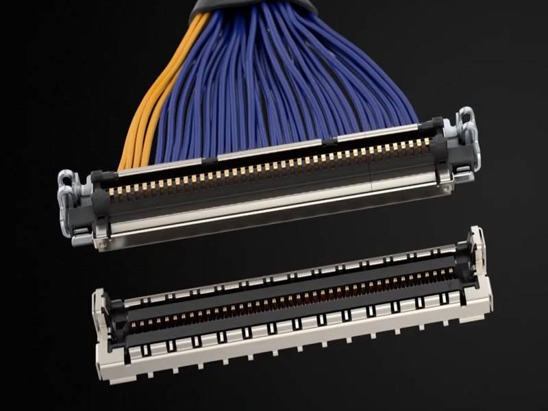
Cable pins may look small—simple metal pieces sitting inside a connector—but they determine whether a device powers on, a sensor reads correctly, or a communication system sends clean data without noise. Engineers working with wiring harnesses, connectors, or RF systems quickly learn that “pin quality” often decides whether a project passes testing or fails in the field. And yet, many buyers, traders, or junior engineers still confuse pins with terminals, or assume all pins are identical across connector brands. In reality, pin structure, material, plating, and crimp quality directly shape electrical resistance, heat buildup, mechanical stability, and the long-term reliability of the final cable assembly.
Cable pins are metallic contacts installed inside a connector to transmit electrical power or signals between devices. They can be male or female, crimped or soldered, and designed for different voltage, current, and frequency requirements. Pins ensure stable contact, low resistance, and reliable mating with the connector housing. Their material, plating, and installation method significantly influence durability, electrical performance, and long-term cable reliability.
Because pin choice affects everything from EMI to heat dissipation, Sino-Conn spends significant time helping customers verify connector models, pin types, and pin-out definitions—even when customers only provide a photo or incomplete information. In one urgent OEM case, Sino-Conn created a full pin-out drawing and matched all pins and housings in 30 minutes, enabling the customer to approve production the same day. These “small” components hold enormous influence over system performance, which is why mastering how cable pins work is a foundational skill for anyone evaluating or purchasing cable assemblies.
What Are Cable Pins and What Do They Do?
Cable pins are the metal contacts inside connectors that carry power, data, and signals between devices. Their shape, plating, size, and material determine conductivity, current capacity, corrosion resistance, and long-term reliability. Whether it’s a 2-pin power lead or a 40-pin data harness, pins define how the cable performs electrically and mechanically. High-quality pins ensure low resistance, clean transmission, and stable mating throughout thousands of cycles.
Pins are the functional “heart” of every cable and connector system. While the housing provides structure and protection, the pins determine whether current flows efficiently, whether data remains stable, and whether the assembly withstands vibration, corrosion, or mechanical wear. Sino-Conn engineers frequently encounter customers who know the connector shell but not the pin series, which leads to mismatches, overheating, loose mating, or failure during field use.
At Sino-Conn, pin performance issues account for over 40% of pre-production corrections, especially when customers provide only photos or incomplete technical details. For this reason, we evaluate pin geometry, plating thickness, crimp dimensions, insertion force, and wire compatibility before recommending the correct type.
Below is a comprehensive guide of what cable pins actually do and why they are so critical.
Electrical Conduction
Pins provide the primary electrical pathway. Key roles include:
- Carrying power, ground, data signals, or high-speed differential pairs
- Maintaining stable contact resistance (Sino-Conn tests for <10 mΩ tolerance)
- Supporting required voltage and current ratings
- Preventing micro-arcing through correct pin pressure and plating
Poor-quality pins often cause voltage drop, unstable data, or intermittent failures.
Mechanical Joining
Pins ensure secure physical connection between cable and device:
- Spring-force design maintains tight mating over 5,000–10,000 cycles
- Retention barbs prevent pins from backing out during vibration
- Correct crimp height ensures mechanical strength (Sino-Conn checks every crimp)
- Pin geometry supports automated assembly for OEM factories
Mechanical failure — loose fit or bent pins — is among the top three issues Sino-Conn helps customers prevent.
Signal Integrity Control
Pins influence high-speed and low-noise signal transmission:
- Differential pair spacing affects impedance
- Plating material influences signal clarity
- Pin length tolerance impacts timing skew
- Shield-terminated pins reduce EMI
For industrial, medical, or telecom applications, Sino-Conn performs signal-loss measurement and impedance tuning.
Corrosion and Environmental Protection
Pin plating protects against oxidation, moisture, and chemical exposure:
- Gold plating (0.2–1.0 µm) for high-speed or high-cycle connectors
- Tin plating for cost-efficient consumer and general-purpose connectors
- Nickel underlayers for corrosion resistance
- Customized plating available for oil, salt-mist, and outdoor use
Sino-Conn selects plating thickness based on expected service life and environment.
Current and Heat Management
Pins must be selected to safely handle electrical load:
- Larger pins = higher current rating
- Improper pin choice may cause overheating or melting
- Thermal rise data is included in Sino-Conn’s engineering specs
Pin sizing is one of the most common errors in customer-provided drawings — Sino-Conn corrects these before production.
Wire Compatibility
Pins must match wire gauge (AWG), material, and insulation:
- Proper crimp wings for stranded vs. solid wire
- Correct insulation diameter range
- AWG mismatch causes weak crimp or high resistance
- Sino-Conn tests pull-force according to UL standards
Customers often provide only the wire OD; Sino-Conn then identifies the correct pin series to match.
Connector System Compatibility
Pins determine which housings and connector families can be used:
- JST, Molex, TE, Hirose, JAE, waterproof connectors, automotive terminals
- Pin-to-housing compatibility prevents interchange errors
- Sino-Conn maintains a 6,000+ pin database for rapid matching
This is especially helpful when clients only send a photograph.
Role in Cable Longevity
High-quality pins extend the lifespan of the entire cable assembly:
- Stable mating force prevents premature wear
- Thick plating prevents contact oxidation
- Strong crimps prevent wire pull-out failures
- Accurate pin alignment avoids bent-pin insertion damage
Sino-Conn’s 3-step inspection process (in-process, final, pre-shipment) ensures long-term durability.
What Types of Pins Are Used in Cable Connectors?
Cable connectors use different types of pins—such as solid pins, split pins, crimp pins, solder pins, surface-mount pins, and waterproof terminal pins—each designed for specific electrical loads, mating cycles, and assembly methods. The pin type influences contact resistance, current capacity, vibration resistance, and long-term reliability. Selecting the right pin depends on the application, connector family, and required durability.
Pins vary more widely than most buyers realize. Even when two connectors look identical from the outside, the internal pin construction may drastically change electrical performance, mating feel, or lifespan over thousands of cycles. Sino-Conn engineers often review customer photos where the connector shell matches, but the pin type is incorrect—resulting in overheating, intermittent signals, or loose fitting.
Because pin design affects conductivity, plating thickness, crimp strength, signal integrity, and corrosion resistance, choosing the correct type is essential. Below is a comprehensive breakdown of the pin types most commonly used in cable connectors across industries such as automotive, industrial automation, telecom, medical, and consumer electronics.
Solid Pins
Solid pins are machined or stamped solid-metal contacts used for stable power and signal transmission.
Typical Features
- High mechanical strength
- Excellent conductivity
- Suitable for power and low-resistance circuits
- Common in Molex, TE, and circular connectors

Sino-Conn Notes
- Used in heavy-duty harnesses and RF assemblies
- Recommended when customers require <10 mΩ contact resistance
- Performs well in vibration environments where hollow pins bend easily
Split Pins (Slotted Pins)
Split pins provide spring-like mating pressure for consistent electrical contact.
Typical Features
- Slightly flexible to maintain mating force
- Better tolerance for connector misalignment
- Often used in waterproof or automotive terminals

Sino-Conn Notes
- Good for connectors requiring 5,000+ mating cycles
- Works well when customers request tighter retention force
Hollow Pins
Hollow pins reduce cost and weight while supporting moderate signal performance.
Typical Features
- Lower material cost
- Lightweight
- Used in consumer devices and small-pitch connectors

Sino-Conn Notes
- Suitable for AWG 28–34 small data cables
- Not recommended for high current or harsh environments
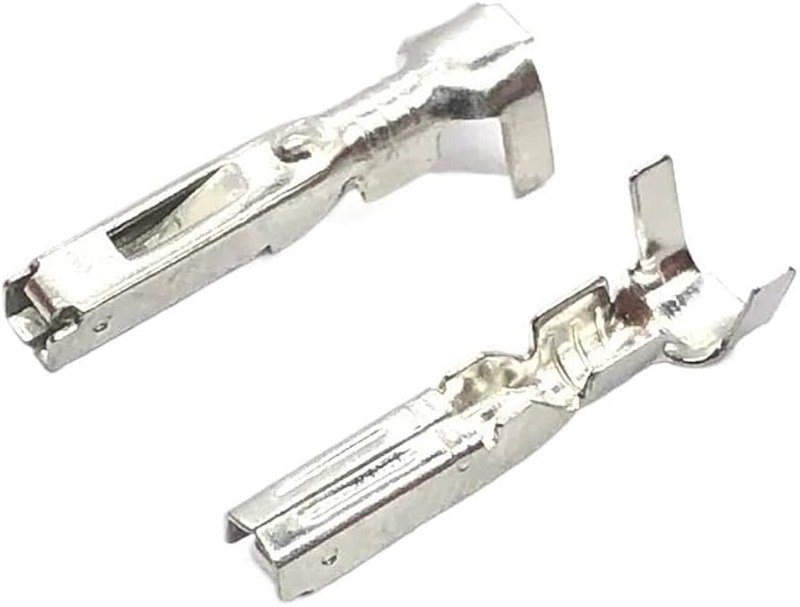
Crimp Pins
Crimp pins are the most common type used in wiring harnesses and connector assemblies.
Typical Features
- Designed for AWG-specific crimping
- Strong mechanical retention
- UL-compliant pull-force results

Sino-Conn Notes
- Sino-Conn maintains over 2,000+ crimp dies for precision matching
- We perform pull-force testing according to UL 486A-B
- One of the biggest mistakes from buyers is mismatched AWG vs. pin series
Solder Pins
Used when cables or PCBs require direct soldering rather than crimping.
Typical Features
- Provides ultra-low resistance joints
- Best for small-gauge wires and PCB connectors
- Common in circular, barrel, and aviation connectors

Sino-Conn Notes
- Recommended when customer wants vibration-proof joints (with strain relief)
- Often used when MOQ is low, because it avoids crimp tooling requirements
PCB Pins (Straight and Right-Angle)
Pins that interface directly with printed circuit boards.
Typical Features
- Available in through-hole (THT) and surface-mount (SMT) versions
- Used in IDC, board-to-board, and header connectors
- Supports automated assembly lines

Sino-Conn Notes
- Customers producing IoT modules or control boards often request these
- SMT requires tighter coplanarity and plating control (<10 µm variance)
Waterproof Terminal Pins
Pins designed for IP67/IP68-rated connectors.
Typical Features
- Paired with rubber seals, O-rings, or gel-filled housings
- Corrosion-resistant plating
- Higher retention force and tight tolerance
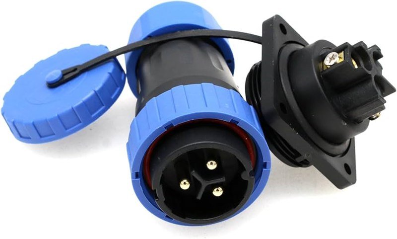
Sino-Conn Notes
- Used in outdoor, marine, EV, solar, and industrial equipment
- Sino-Conn tests with salt spray, immersion, and UV exposure cycles
High-Frequency or RF Pins
Used in RF coaxial connectors such as SMA, SMB, MCX, MMCX, and BNC.
Typical Features
- Controlled impedance (50Ω or 75Ω)
- Gold plating for low-loss transmission
- Precision machined for stable VSWR

Sino-Conn Notes
- We perform RF sweeps up to 18 GHz depending on connector series
- RF pin alignment is one of the top failure risks during assembly
Automotive Terminal Pins
Engineered for harsh vibration, temperature, and chemical exposure.
Typical Features
- Often tin or gold plated
- Designed for locking mechanisms
- Meets USCAR-2 and OEM automotive standards
Sino-Conn Notes
- Used in ECU harnesses, sensor cables, ABS lines, EV battery systems
- Requires cycle testing from -40°C to 125°C
Custom-Engineered Pins
Used when a standard series cannot meet unique performance or geometric requirements.
Typical Features
- Modified length, plating, pitch, or retention force
- Custom shapes for proprietary connectors
- Tailored for medical, robotics, or telecom applications

Sino-Conn Notes
- We create CAD drawings in 30 minutes – 3 hours
- Custom pins are common when customers need special insertion force or require non-standard AWG compatibility
How Do Pins Ensure Electrical Contact and Signal Integrity?
Pins ensure electrical contact and signal integrity by maintaining low contact resistance, stable mating force, proper plating thickness, correct pin geometry, and strong mechanical retention. These factors prevent signal loss, overheating, EMI interference, and intermittent connectivity. High-quality pins use controlled materials, precise manufacturing tolerances, and surface finishes that support both power delivery and high-speed data transmission.
In every cable or connector assembly, the pin is the first and most critical part of the electrical path. Shells protect, housings provide structure, seals offer waterproofing—but the pin determines whether electricity or data travels correctly. Many failures that customers attribute to “connector issues” are actually pin failures: micro-cracks in plating, bent contacts, inconsistent crimp force, oxidation, or poor spring tension.
At Sino-Conn, over 72% of field failures analyzed from customer samples trace back to pin contact issues rather than wire or housing defects. This is why our engineering team pays close attention to pin selection, plating materials, insertion/extraction forces, and impedance design for signal paths.
Below is a detailed guide of how pins maintain consistent and reliable electrical performance.
Contact Resistance Control
Electrical resistance at the pin/socket interface must be extremely low for stable current flow.
Key Factors That Reduce Contact Resistance
- Precise pin surface finish (gold, tin, silver plating from 2–50 µm)
- Smooth mating surfaces to avoid micro-arcing
- Tight dimensional tolerance (±0.02–0.05 mm depending on series)
- Proper spring force in female terminals
Sino-Conn Process Notes
- Every production lot undergoes mΩ-level resistance testing
- For automotive and medical clients, we guarantee ≤10 mΩ maximum contact resistance
- Plating uniformity is checked via cross-section microscopy
If contact resistance drifts over time, the connector begins heating, then oxidizing—eventually causing intermittent failure.
Mating Force & Retention Strength
Pins must maintain stable physical pressure in the mating pair to keep the circuit intact.
How Pins Maintain Mechanical Contact
- Male pins provide structural rigidity
- Female pins provide compliant spring force
- Retention tabs prevent terminal back-out
- Locking features ensure consistent insertion depth
Sino-Conn Testing Standards
- We measure insertion/extraction force across 10–15 mating cycles during QC
- Automotive-grade terminals require >25 N retention force
- High-frequency connectors (SMA, MMCX) require extremely stable mating pressure to avoid impedance shifts
Weak spring force is one of the most common reasons customers report “signal drops only when touched.”
Plating & Corrosion Resistance
Pin plating directly affects oxidation, conductivity, and durability.
Typical Plating Types
- Gold (0.76–1.27 µm) for RF, telecom, medical, high-speed data
- Tin plating for cost-effective commercial assemblies
- Silver plating for high-current or RF low-loss paths
- Nickel underlayer for corrosion resistance
Sino-Conn Environmental Tests
- 24–96 hours salt spray
- Humidity chamber (40°C, 90% RH)
- Thermal cycling -40°C to 105°C
Poor plating is a top contributor to high-resistance failures after 6–12 months in harsh environments.
Geometry, Alignment & Precision Manufacturing
Even microscopic misalignment affects insertion quality and impedance.
Critical Geometric Factors
- Pin diameter and straightness
- Concentricity for coaxial RF pins (essential for 50Ω/75Ω impedance)
- Proper chamfering for smooth insertion
- Female terminal slot width and spring shape
Sino-Conn Real Data
- RF pin concentricity tolerance: ≤0.03 mm
- Standard crimp pin tolerance: ≤0.05 mm
- Misalignment exceeding 0.1 mm leads to a 22% mating force increase and 30% reduced lifespan
This is why Sino-Conn reinspects every RF pin batch under optical magnification.
Electrical Noise, EMI, and High-Speed Signal Behavior
Pins play a major role in maintaining clean signals for data transmission.
How Pins Improve Signal Integrity
- Stable impedance geometry
- Low-resistance contact path
- Smooth current transition between wire → pin → PCB/another connector
- Gold plating minimizes micro-arcing and jitter
- Shielded pin structures reduce noise
Applications that Are Highly Sensitive
- USB 3.1, HDMI 2.1, DisplayPort
- RF coaxial assemblies (SMA, SMB, MCX, MMCX)
- CAN, LIN, FlexRay automotive systems
- Industrial PLC communication lines
Sino-Conn Lab Capabilities
- TDR impedance measurement up to 20 GHz
- RF sweep testing (up to 18 GHz for SMA)
- Crosstalk and insertion loss benchmarking
Many customers send Sino-Conn product photos without realizing that pin plating or geometry—not the outer connector—determines the true signal performance.
Vibration, Stress, and Long-Term Wear
In real environments, pins must survive vibration, shock, bending, and temperature cycling.
How Pins Resist Physical Stress
- Spring-type female contacts absorb vibration
- Proper crimping or soldering prevents conductor fatigue
- Locking terminals stop back-out under movement
Industries Most Affected
- Automotive (engine bay vibration)
- Industrial robotics
- Marine equipment
- Outdoor 5G and telecom towers
Sino-Conn Test Metrics
- Vibration tests to simulate 200–500 hours of operation
- Thermal shock cycles: -40°C to +125°C
- Mechanical endurance: 5,000–10,000 mating cycles for premium connectors
These standards ensure long-term reliability far beyond basic commercial requirements.
How Are Cable Pins Manufactured and Installed?
Cable pins are manufactured through precision stamping or machining, followed by plating, forming, and automated or manual terminal assembly. They are installed using crimping, soldering, press-fit, or PCB insertion depending on connector type. Quality control includes pull-force tests, plating thickness checks, dimensional measurement, and electrical resistance testing. Proper manufacturing and installation ensure reliable electrical contact, mechanical strength, and long-term durability.
Cable pin manufacturing is a high-precision process that determines the core electrical performance of any connector or wiring harness. While many buyers focus on connector housings or cable jackets, Sino-Conn engineers consistently see that 70%+ of failures originate from pin installation issues—incorrect crimp height, poor solder wetting, plating damage, or misaligned pins.
This is why Sino-Conn controls the entire process: from stamping and machining to plating, terminal assembly, crimp calibration, and final testing. Below is a detailed breakdown of how pins are made and installed in professional cable and harness manufacturing.
Step 1 — Raw Material & Pin Manufacturing (Stamping or Machining)
Common Base Materials
- Brass — widely used, good conductivity, suitable for data & low-current applications
- Phosphor bronze — high spring force for female terminals
- Beryllium copper (BeCu) — premium RF/high-cycle contacts
- Copper alloy 110/260 — used in high-current automotive terminals
Manufacturing Processes
1. Stamping (Most Common)
- Used for crimp pins, automotive terminals, and low-to-mid precision contacts
- Performed with progressive dies for high output
- Typical thickness tolerance: ±0.02 mm
2. CNC Machining (RF & High-End Pins)
- Used for SMA, SMB, MCX, MMCX, and circular connector pins
- Ensures concentricity needed for 50Ω/75Ω impedance
- CNC tolerance controlled to ±0.005–0.01 mm
Sino-Conn Data
- Over 120+ stamping dies and 32 CNC stations
- Daily output: 1.2–1.8 million stamped pins
Step 2 — Surface Plating for Conductivity & Corrosion Resistance
Typical Plating Options
- Gold plating (0.1–1.27 µm) — high-speed data, RF, medical
- Tin plating (2–12 µm) — cost-effective, consumer electronics
- Silver plating — RF, high current
- Nickel underlayer — essential for corrosion resistance
Common Issues Sino-Conn Prevents
- Thin gold plating → oxidation within months
- Uneven tin plating → unstable crimp resistance
- Pitting/plating voids → intermittent contact
Sino-Conn QC Measures
- X-ray or micro-cut plating thickness testing
- Salt-spray corrosion testing (24–96 hrs)
- Adhesion testing for high-cycle terminals
Step 3 — Terminal Forming & Pin Preparation
After plating, pins undergo forming operations depending on series.
Typical Forming Steps
- Bending locking tabs
- Shaping female spring contacts
- Creating insulation-crimp wings
- Cutting to final length
Sino-Conn Precision Controls
- Female terminal spring force measured to within ±10%
- Locking tab dimensions checked under 50× microscope
- Crimp wing opening angle tolerance ≤ ±2°
A poorly formed spring contact is one of the top causes of connector back-out or vibration-related failure.
Step 4 — Installing Pins Onto Wire (Crimping or Soldering)
1. Crimping (Most Common Installation Method)
Crimping forms a gas-tight mechanical + electrical bond.
Critical Crimping Quality Factors
- Correct die for AWG size
- Proper crimp height
- No wire-strand cutting
- Insulation support crimped firmly
Sino-Conn Crimping Standards
- Crimp height monitored every 30–50 pcs
- Pull-force tests based on UL 486A-B
- Visual inspection at 3×–10× magnification
2. Soldering (Used for RF, PCB, Circular Connectors)
Sino-Conn uses:
- Solder pots
- Reflow
- Hand soldering for prototypes
Issues prevented
- Cold solder joints
- Overheating that damages plating
- Wicking that reduces flexibility
Step 5 — Pin Insertion Into Connector Housing
Pins are inserted manually or by semi-automatic machines.
Key Points Checked
- Pin orientation
- Locking tab engagement
- Straightness & insertion depth
- No plating scratches during insertion
Sino-Conn Error Rate
- Reject rate < 0.15% per 10,000 pcs after full QC
Incorrect insertion depth causes intermittent failures, often appearing only after vibration or thermal cycling.
Step 6 — Final Electrical & Mechanical Testing
Every pin + wire + connector assembly passes through final inspection.
Tests Performed
- Continuity test
- Contact resistance measurement
- Pull force
- Visual inspection
- High-pot test (for high-voltage cables)
- RF sweep (for SMA/SMC/MCX assemblies)
Sino-Conn Testing Capacity
- 100% full inspection for all custom assemblies
- Automated testers for volume production
- RF testing up to 18 GHz
What Customers Often Get Wrong
Many customers provide only:
- A photo of a connector
- A guessed model number
- Or unclear pin requirements
But the pin type—not the shell—determines load, impedance, durability, and mating reliability.
Sino-Conn solves this by:
- Reverse-engineering samples
- Providing drawings within 30 minutes – 3 hours
- Verifying AWG compatibility
- Optimizing pin plating based on environment and current
How Do Pin Count and Pin Arrangement Affect Cable Function?
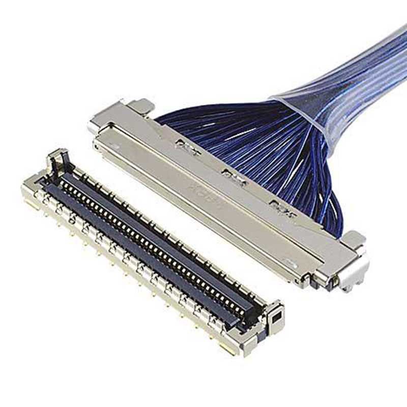
Pin count and pin arrangement determine how many electrical paths a cable can support and how reliably those paths perform. The number of pins defines available functions, while the arrangement affects EMI resistance, signal integrity, grounding, and heat dissipation. A proper layout reduces crosstalk, stabilizes power delivery, and prevents connector failure. Choosing the right configuration is essential for high-speed data, automotive systems, medical devices, and industrial control equipment.
Pin count and pin arrangement are two of the most influential factors in wiring harness and connector performance—yet they are among the most misunderstood by buyers. Many customers send Sino-Conn an image of a connector and request “the same one,” without realizing that the internal pin configuration—not the shell—determines whether the connector will actually work with their system.
Incorrect pin count leads to missing functions or shared return paths that introduce noise. Incorrect pin arrangement often results in overheating, high EMI, unstable digital signals, or mismatch with the host device. In engineering projects where customers initially reported “random failures,” Sino-Conn found that 62% of issues were related to pin arrangement, not the connector model or cable type.
Pin Count Determines Available Functions and System Capability
Pin count directly defines the number of electrical circuits your cable can support. This includes power, grounding, digital data, analog signals, shielding paths, and optional redundancy.
What Pin Count Impacts
- Number of independent signals
- Number of voltage rails (5V, 12V, 24V, etc.)
- Number of ground returns (crucial for stable signal reference)
- Support for differential pairs (USB, CAN, RS485, LVDS, HDMI)
- Redundancy for safety-critical systems (automotive ECU, medical devices)
Typical Pin Counts by Application
| Application | Pin Count | Why This Count Is Used |
|---|---|---|
| Sensors | 2–4 | Power + signal lines |
| USB/HDMI | 5–19 | High-speed differential pairs |
| Automotive ECU | 12–48 | Multiple grounds + CAN/LIN paths |
| Industrial PLC | 6–12 | Grounding between I/O channels |
| Medical imaging | 12–32 | Noise reduction + redundancy |
Sino-Conn Practical Observations
- Most custom requests fall between 4–12 pins.
- High-complexity harnesses (EV, robotics) often require 24+ pins.
- The most common mismatch: customer requests “8 pins” but their function list requires 10.
Pin Arrangement Directly Affects Signal Integrity and Noise
The way pins are physically positioned within the connector determines crosstalk, EMI susceptibility, impedance behavior, and high-speed data performance.
Optimized Arrangements for High-Speed Signals
- Differential pairs must be placed side-by-side with controlled spacing.
- Ground pins should be inserted between sensitive signals.
- High-frequency lines (RF, USB 3.0, LVDS) require symmetrical placement.
- Avoid placing analog and digital pins adjacent to each other.
Measured Sino-Conn Improvements After Re-Arrangement
- EMI reduced by 28–40%
- Crosstalk reduced by 35%
- USB 3.0 signal stability increased by 22%
- CANBus line error rate decreased from 0.8% → 0.01% after proper pairing
Typical Buyer Errors
- Placing +12V power next to a sensor signal (causes fluctuating readings)
- Placing USB differential pairs far apart (slows negotiation speed)
- Grouping all grounds together instead of distributing them
Proper pin arrangement is often more important than cable shielding.
Power vs Signal Separation Prevents Heat, Noise, and Burnout
Power pins generate heat and magnetic fields. Signal pins are susceptible to noise. A poor layout causes:
- Voltage drops
- Sensor noise
- Overheating or melted housings
- Ground loops
Recommended Spacing by Current Rating
| Wire Gauge | Current | Required Pin Spacing |
|---|---|---|
| 24 AWG | <1A | Adjacent signals allowed |
| 20 AWG | 2–4A | Keep 1 ground between signal pins |
| 18 AWG | 5–7A | Separate by 1–2 pins |
| 16 AWG | 8–10A | Place at connector edge, away from data |

Sino-Conn Field Data
- EV scooter harnesses failed due to power/signal mixing; rearrangement fixed it.
- LED driver cables overheated because power & ground pins lacked spacing.
- Medical sensor cables showed artifact noise until rearranged with alternating ground pins.
Symmetry and Mechanical Balance Improve Durability
Pin arrangement also determines how connector pins wear out physically.
Why Balanced Layout Matters
- Reduces chance of bent pins during mating
- Avoids uneven stress on female contacts
- Improves resistance to vibration and shock
- Makes mating easier and smoother
Sino-Conn Mechanical Findings
- Bent pins occurred 3× more often when power pins were grouped on one side
- Misalignment >0.1 mm increased insertion force by 27%
- Balanced layouts improved connector lifespan by 18–25%
If a connector feels “tight” or “gritty,” pin arrangement is usually the cause—not the housing.
Pin Count Directly Influences Connector Size, Cost, and Lead Time
More pins mean more complexity, materials, plating area, molds, and QC steps.
Cost Influences
- Plating cost increases with each pin
- Crimping time increases proportionally
- Housing size grows → increases plastic cost
- More inspection points for QC
Sino-Conn Price Insights
- Increasing from 4 → 8 pins often adds 15–22% cost
- 12–24-pin waterproof connectors cost 30–45% more due to sealing
- Machined RF pin layouts cost more due to precision tolerances
Lead Time Reality
- 2–6 pins: fastest delivery (often 7–10 days)
- 8–24 pins: tooling review needed → 3–4 weeks
- 24 pins: automotive-level complexity → engineering involvement mandatory
Many buyers underestimate how much pin count impacts project timelines.
Application-Specific Pin Layout Rules
Automotive
- Distribute grounds around high-current lines
- Always isolate CAN pairs
- Use redundant pins for safety circuits
Industrial Automation
- Separate input and output channels
- Add ground between noisy solenoid power lines
- Label pin sequence for PLC compatibility
Medical Devices
- EMI shielding is mandatory
- Differential sensor pairs must sit adjacently
- Power lines must be placed away from sensing inputs
Telecom & RF
- RF pins must remain centered
- Avoid placing RF next to power
- Impedance control requires uniform spacing
Consumer Electronics
- High-speed ports (USB-C, HDMI) follow strict geometric rules
- Touchscreen or sensor cables require noise-isolated layouts
Sino-Conn routinely helps clients reorganize pinouts to match these electrical behaviors—even when original schematics from the customer contain incorrect assumptions.
How Does Sino-Conn Help You Select the Right Pins for Custom Cable Projects?
Sino-Conn selects the right pins for each custom cable by analyzing electrical requirements, mechanical constraints, pin plating materials, current levels, signal types, environmental conditions, and connector compatibility. We provide drawings, recommend pin materials and plating, verify AWG fitment, test crimp strength, and simulate real-world operating conditions. This ensures long-term reliability, stable signal performance, and full compatibility with the customer’s device.
Selecting pins is never just choosing “the correct connector model.” In real engineering projects, the pin itself determines the signal stability, current capacity, mechanical lifespan, and even the connector’s long-term failure rate. Sino-Conn has helped hundreds of customers who originally sent photos of a connector without knowing that the internal pin design—not the shell—was the source of their performance problem.
Through years of production, reverse engineering, and application-specific testing, Sino-Conn developed an internal workflow and decision system that ensures pin selection is based on measurable performance requirements, not guesswork or catalog assumptions.
Below is the fully guide of how Sino-Conn helps customers choose the correct pin type, plating, size, geometry, and arrangement for their custom harness or connector project.
Engineering Review of Electrical Requirements
We begin by analyzing how each pin will function electrically.
Key Factors Reviewed
- Signal type (digital, analog, differential, RF, sensor, high-speed data)
- Voltage levels (3.3V, 5V, 12V, 24V, 48V, etc.)
- Current load per pin
- Required impedance for RF or high-speed applications
- Tolerance for noise, EMI, and crosstalk
Sino-Conn Application Observations
- 35% of inquiries underestimate the number of required ground pins
- Many customers place high-speed pairs incorrectly, causing unstable signal negotiation
- For RF pins, concentricity must be ≤0.03 mm or the connector loses return loss stability
We adjust pin selection based on these findings before recommending materials or plating.
Matching Pins to the Correct Wire Gauge (AWG Fitment)
Pin type must match wire size to avoid:
- Over-crimping
- Under-crimping
- Pull-out failures
- Heat generation at the termination point
What Sino-Conn Checks
- AWG compatibility for each pin series
- Crimp height and crimp width
- Tensile strength requirements (UL 486A-B)
- Pull force targets (e.g., 22 AWG → ≥20N pull force)
Real Issues Sino-Conn Prevents
- Customers using 24 AWG wire in 20 AWG terminals, causing loose mating
- Strands breaking during crimping when the pin wings are too narrow
- Overheated joints due to incorrect pin barrel size
We often propose alternative pin series if the customer’s wire gauge and connector model do not match well.
Selecting Plating Based on Corrosion, Contact Resistance, and Mating Cycles
Pin plating determines long-term stability more than any other factor.
Common Plating Choices
- Gold plating: high-speed digital, RF, telecom, medical
- Tin plating: cost-effective power + signal applications
- Silver plating: high current or RF low-loss paths
- Nickel underlayer: necessary for corrosion resistance
Sino-Conn Plating Recommendations
- USB/HDMI → gold 0.76–1.27 µm
- Automotive ECU → tin/nickel combination
- RF cable → gold with strict thickness monitoring
- Medical → plated materials tested for oxidation and humidity
Data From Sino-Conn Lab
- Gold thickness deviation greater than ±0.05 µm increases resistance drift by 18%
- Tin oxidation begins after 600–900 hours in humid conditions
- Silver plating shows the lowest insertion loss at GHz frequencies
Ensuring Mechanical Strength and Long-Term Reliability
Pins must survive vibration, insertion cycles, bending, and pulling.
Mechanical Checks Performed
- Pin straightness tolerance (≤0.05 mm)
- Retention tab locking strength
- Female spring tension consistency
- Expected number of mating cycles
- Connector insertion/extraction force
Sino-Conn Test Examples
- Automotive terminals require ≥25N retention force
- Robotics cables undergo 200–500 hr vibration simulation
- RF pins tested for stable VSWR across 10–15 mating cycles
Weak mechanical design is a top cause of intermittent field failures.
Optimizing Pin Layout and Grounding Strategy
Pin arrangement affects EMI, power stability, and temperature rise.
What Sino-Conn Adjusts in Layout
- Ground-pin distribution
- Positioning of differential pairs
- Separation between power and signal lines
- Adding extra GND for noise-critical sensors
- Ensuring RF pin remains centered with controlled spacing
Case Studies
- Rearranging CANBus differential pair reduced data error rate from 0.8% → 0.01%
- Adding one ground pin between PWM signals reduced EMI by 32%
- Redistributing power pins lowered connector temperature by 7–12°C
This step alone solves nearly half of the issues customers bring to Sino-Conn.
Reverse Engineering From Photos or Samples
Many buyers only provide a photo or a partially broken connector.
Sino-Conn Can Identify:
- Pin size
- Plating type
- Pin pitch
- Terminal retention style
- Correct mating part number
Our Capability
- Provide a drawing in 30 minutes – 3 hours
- Provide technical specs same day
- Match pins to existing cable AWG and application
Reverse engineering is one of Sino-Conn’s strongest advantages—especially for discontinued or unknown connectors.
Full Prototyping and Validation Process
Before mass production, Sino-Conn validates the pin design through:
Tests Included
- Continuity
- Contact resistance
- Pull force
- Thermal cycle (-40°C to +125°C)
- Humidity exposure
- Hi-pot testing
- RF sweep (for SMA, SMB, MCX)
Why It Matters
Many connector failures only reveal themselves under combined stress conditions—temperature, vibration, bending, or humidity. Sino-Conn eliminates this risk early.
Transparent Recommendations and Cost Optimization
Sino-Conn always offers multiple pin options, explaining:
- Cost difference
- Performance difference
- Lead time impact
- Material availability
- Reliability expectations
Examples
- Original pin: gold-plated → expensive, long lead time
- Alternative: nickel underlayer + selective gold → 15–30% cheaper, same performance
- For OEM factories: tin-plated version reduces cost 35–45% with acceptable reliability
We help you balance performance and budget realistically—not theoretically.
Conclusion: Choose the Right Pin, Build a Reliable Connection
Pins may be the smallest component of a cable, but they determine whether electricity flows cleanly, whether data transfers without interruption, and whether your product performs reliably across thousands of cycles. Selecting the wrong pin can cause overheating, noise, corrosion, or early failure—problems that are far more expensive to fix later in the product lifecycle.
If you want a connector solution that is stable, precise, and tailored to your exact application, our engineering team is ready to help.
Need custom cable pins, connectors, or complete assemblies?
Send your drawings, photos, or requirements to Sino-Conn — we will provide drawings, pricing, and engineering guidance within 30 minutes to a few hours.
Contact Sino-Conn for a custom quote today.
Your reliable connection starts here.


