 Skip to content
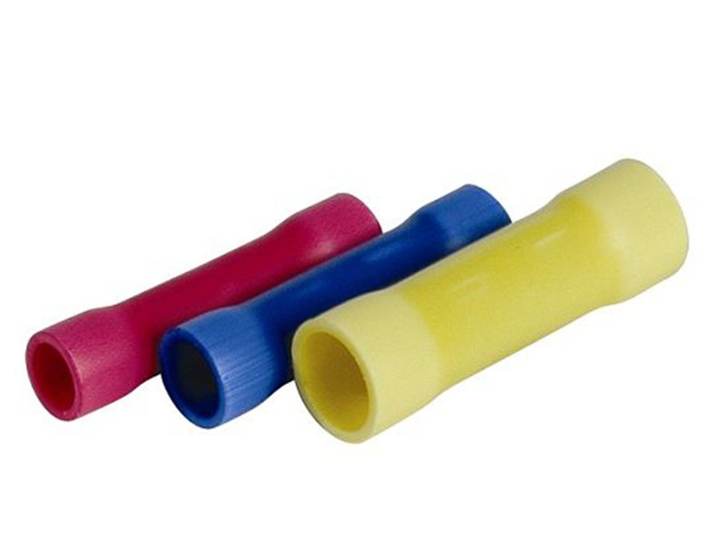
In wire harness and cable assembly work, failures rarely happen where people expect them. Engineers often focus on cable types, conductor materials, insulation ratings, or connector brands, while overlooking something far more basic: how two wires are joined together. In real-world applications—especially automotive, industrial control, and power distribution—the weakest point is often not the cable itself, but the splice hidden inside the harness.
Butt connectors sit right at this intersection of simplicity and risk. They look straightforward, inexpensive, and easy to use. Strip the wires, crimp both ends, and move on. Yet in production environments, improperly selected or poorly crimped butt connectors are responsible for a significant share of intermittent faults, voltage drops, overheating incidents, and early field failures. These issues are especially costly because they are difficult to diagnose once the harness is installed.
Butt connectors are used to join two wires end-to-end in wire harness and cable assembly applications. To use them correctly, you must select the proper connector size for the wire gauge, strip the insulation accurately, crimp with the correct tool and force, and verify the connection through mechanical and electrical testing. Proper usage ensures low resistance, high mechanical strength, and long-term reliability.
For manufacturers, OEMs, and engineers, understanding how to use butt connectors is not about DIY wiring—it is about process control, repeatability, and reliability at scale. The difference between a harness that passes initial testing and one that survives years of vibration, heat, and current load often comes down to this small, overlooked component. Let’s break down how butt connectors really work, where they belong, and how professionals use them correctly.
What Are Butt Connectors and What Are They Used For?
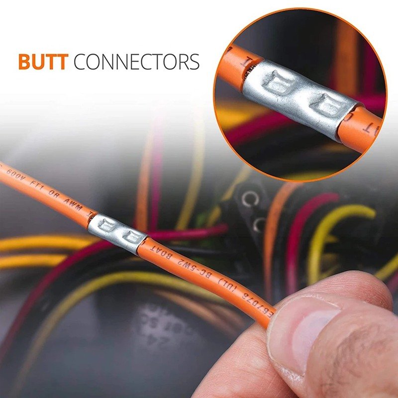
Butt connectors are wire-to-wire crimp connectors designed to join two conductors end-to-end. They are commonly used in wire harnesses to extend wire length, repair damaged conductors, or create inline splices without soldering. Butt connectors are widely applied in automotive, industrial, power, and control wiring where speed, consistency, and mechanical reliability are required.
What Is a Butt Connector in Wire-to-Wire Connections?
A butt connector is a cylindrical metal sleeve—typically copper or tinned copper—covered by an insulating sleeve made of PVC, nylon, or heat-shrink material. Each end of the connector accepts one stripped wire conductor. When crimped correctly, the metal sleeve cold-forms around the copper strands, creating a gas-tight mechanical and electrical connection.
Unlike terminal connectors that interface with devices or boards, butt connectors are inline splices. They do not “mate” with anything; they permanently join two wires into a continuous conductor. This makes them especially common in wire harness manufacturing, where multiple wire segments must be joined inside a loom or overmolded section.
From a manufacturing perspective, butt connectors are valued for three reasons:
- They require no solder or curing time
- They support high-throughput crimping operations
- They produce repeatable results when tooling and parameters are controlled
However, these benefits only exist when butt connectors are used within their design limits. Outside those limits, they become a reliability risk.
Where Are Butt Connectors Commonly Used in Cable Assemblies?
Butt connectors are most commonly found in wire harness assemblies, not finished interface cables like USB, coaxial, or LVDS cables. Typical applications include:
- Automotive harness repairs and extensions
- Industrial control wiring inside cabinets
- Power harnesses for appliances and equipment
- Lighting and HVAC wiring
- Low-to-medium voltage distribution systems
In custom cable assembly factories, butt connectors are often used inside looms, conduits, or overmolded sections, where the splice is not meant to be serviced. This is why upfront correctness matters: once installed, the splice is usually inaccessible.
It is also worth noting where butt connectors are not appropriate. High-frequency signal cables, impedance-controlled lines, and medical-grade assemblies often prohibit butt splices entirely, favoring soldered or molded joints instead. Understanding this boundary is critical for correct application.
Which Types of Butt Connectors Are Available?
Butt connectors vary by conductor size, material, insulation type, and environmental protection. Common types include insulated, non-insulated, and heat-shrink butt connectors, each suited for different wire gauges, voltage levels, and operating conditions. Selecting the correct type is essential for electrical performance and long-term durability.
Which Materials Are Used in Butt Connectors?
The conductive core of a butt connector is typically made from copper or brass, often plated with tin to resist corrosion. Copper offers excellent conductivity and crimpability, while tin plating improves oxidation resistance, especially in humid or automotive environments.
Insulation materials vary widely:
- PVC: low cost, suitable for general indoor use
- Nylon: higher temperature resistance and mechanical strength
- Heat-shrink polyolefin: provides environmental sealing and strain relief

In industrial and automotive harnesses, heat-shrink butt connectors are increasingly preferred because they combine electrical connection and environmental protection in one operation.
Which Butt Connector Types Suit Different Wire Gauges?
Butt connectors are sized according to wire gauge ranges. Using the wrong size is one of the most common causes of failure.
| Wire Gauge (AWG) | Typical Connector Color | Application Range |
|---|---|---|
| 22–18 AWG | Red | Signal, low power |
| 16–14 AWG | Blue | Control, lighting |
| 12–10 AWG | Yellow | Power circuits |
Professional manufacturers do not rely on color alone. They verify conductor strand count, insulation diameter, and crimp barrel dimensions to ensure compatibility—especially for custom wire types that deviate from standard AWG profiles.
How Do You Choose the Right Butt Connector?
Choosing the right butt connector is not simply a matter of matching colors or wire gauges. In real wire harness and cable assembly projects, the wrong connector choice often leads to failures that appear months later—long after installation—when heat, vibration, or load expose hidden weaknesses.
A correct selection balances wire construction, electrical load, environment, and manufacturing process. Professional manufacturers treat butt connector selection as an engineering decision, not a convenience choice.

Which Wire Characteristics Matter Most When Selecting a Butt Connector?
The starting point is always the wire itself—but not just its nominal gauge.
Key wire characteristics to evaluate include:
- Nominal wire gauge (AWG or mm²)
- Actual conductor cross-section and strand count
- Strand flexibility (solid vs fine-stranded)
- Insulation thickness and hardness
Two wires labeled as the same AWG may behave very differently during crimping. A high-strand-count flexible wire fills the barrel differently than a low-strand-count conductor, even at the same gauge.
| Wire Feature | Why It Matters for Selection |
|---|---|
| Strand count | Affects barrel fill and crimp compression |
| Strand diameter | Influences cold-weld quality |
| Insulation thickness | Determines insertion depth and strain relief |
| Conductor material | Impacts conductivity and corrosion behavior |
In manufacturing environments, wire samples are often test-crimped before final connector approval—especially for custom or non-standard cables.
How Do Electrical Load and Current Rating Influence Connector Choice?
Butt connectors fail primarily due to heat, not voltage.
As current increases, even a small rise in contact resistance can generate significant localized heating at the splice. This heat degrades insulation, relaxes crimp pressure over time, and accelerates oxidation.
When evaluating electrical load, consider:
- Continuous current (not peak current)
- Duty cycle (constant vs intermittent)
- Ambient temperature inside the harness
| Current Range | Typical Risk Level | Recommended Connector Type |
|---|---|---|
| <2 A | Low | Standard insulated butt connector |
| 2–10 A | Medium | Nylon insulated butt connector |
| >10 A | High | Heat-shrink or heavy-duty butt |
For higher-current harnesses, many manufacturers prefer non-insulated connectors with controlled crimp profiles, followed by secondary insulation. This approach offers better heat dissipation and more consistent electrical performance.
Which Butt Connector Materials Are Appropriate for Different Environments?
Environmental exposure often determines connector lifespan more than electrical load.
Common considerations include:
- Temperature extremes
- Moisture or condensation
- Oil, fuel, or chemical exposure
- Vibration and mechanical stress
| Environment Condition | Preferred Connector Construction |
|---|---|
| Indoor, dry | PVC insulated butt connector |
| Elevated temperature | Nylon insulated butt connector |
| Moisture or outdoor use | Heat-shrink butt connector |
| Oil / chemical exposure | Sealed or overmolded splice solution |
Heat-shrink connectors with adhesive lining provide both insulation and environmental sealing, making them common in automotive and industrial harnesses.
How Do Manufacturing Processes Affect Connector Selection?

In production, the “best” connector is not always the most robust—it is the one that can be consistently crimped and inspected.
Manufacturing factors include:
- Availability of compatible crimp tools
- Operator skill level
- Production volume and cycle time
- Inspection and testing capabilities
A connector that requires special tooling or excessive manual adjustment may increase defect rates, even if its theoretical performance is higher.
Experienced manufacturers select connectors that align with their validated processes to ensure repeatability across batches.
When Should You Avoid Using Butt Connectors Altogether?
Choosing the right butt connector also means knowing when not to use one.
Avoid butt connectors when:
- Signal integrity is critical (high-speed or RF cables)
- Impedance control is required
- Continuous flexing or torsion is expected
- Regulatory standards prohibit inline splices
In these cases, soldered joints, welded splices, or molded connections offer better long-term reliability—even if they increase upfront cost.
Why Proper Connector Selection Reduces Long-Term Cost
Incorrect connector selection often appears cheaper at the start, but leads to:
- Field failures
- Troubleshooting labor
- Warranty claims
- Reputation damage
By selecting the right butt connector early—based on real operating conditions rather than assumptions—manufacturers and OEMs significantly reduce total lifecycle cost.
This is why professional cable assembly suppliers evaluate connector choice as part of the overall system design, not as an isolated component decision.
How to Use Butt Connectors Step by Step
Using butt connectors correctly is not a single action—it is a controlled sequence of preparation, crimping, and verification. In professional wire harness manufacturing, failures almost never come from one obvious mistake, but from small deviations across multiple steps. The goal of a proper butt connector process is to create a splice that is mechanically strong, electrically stable, and repeatable across production batches.
Below is a step-by-step breakdown used in real cable assembly and wire harness production environments.
Step 1: Confirm Wire and Connector Compatibility
Before any wire is stripped, the first step is confirmation—not action.
You must verify:
- Wire gauge (AWG or mm²)
- Actual conductor strand count and construction
- Insulation outer diameter
- Butt connector barrel size and material
Relying only on color codes (red / blue / yellow) is risky, especially when using custom or non-standard wires. Two wires labeled as the same AWG can behave very differently during crimping.
Practical check used by manufacturers:
Insert a stripped wire sample into the connector barrel without crimping. The conductor should fill the barrel fully, without excessive looseness or forced compression.
Step 2: Strip the Wire to the Correct Length
Wire stripping is one of the most underestimated steps—and one of the most common sources of defects.
Key requirements:
- Insulation must be removed cleanly
- No conductor strands should be nicked or cut
- Strip length must match the metal barrel length
Over-stripping exposes conductor outside the connector, increasing corrosion risk. Under-stripping prevents full strand engagement, reducing pull strength and conductivity.
| Wire Gauge (AWG) | Recommended Strip Length |
|---|---|
| 22–18 AWG | 4–5 mm |
| 16–14 AWG | 5–6 mm |
| 12–10 AWG | 6–7 mm |
In production lines, automatic wire strippers with strip-length control are preferred to eliminate operator variation.
Step 3: Insert the Wire Fully Into the Butt Connector
Each wire must be inserted until the conductor reaches the center of the connector barrel. Partial insertion is a frequent hidden failure mode.
Best practices:
- Ensure all strands enter the barrel
- No strands should fold back outside the connector
- Insulation should butt up against the barrel entrance (not inside the crimp zone)
In dual-ended butt connectors, both wires should meet near the center of the barrel, creating a continuous electrical path.
Step 4: Select the Correct Crimp Tool and Die
Crimping quality depends more on the tooling than on operator strength.
Requirements:
- Use a crimp tool matched to the connector type (insulated vs non-insulated)
- Use the correct die profile for the barrel geometry
- Avoid generic or worn dies
Professional crimp tools are designed to:
- Apply consistent force
- Complete a full crimp cycle
- Prevent under- or over-crimping
Re-crimping the same connector is strongly discouraged—it damages the cold-welded structure and reduces reliability.
Step 5: Crimp the Metal Barrel (Not the Insulation)
The crimp must deform the metal barrel, not the insulation sleeve.
A correct crimp will:
- Compress strands into a solid mass
- Exclude air (gas-tight connection)
- Lock the conductor mechanically
Common mistakes include:
- Crimping too close to the insulation
- Crimping on the plastic sleeve
- Partial tool cycles due to rushed operation
In factory settings, crimp height or crimp force is often monitored as a quality indicator.
Step 6: Inspect the Crimp Mechanically and Visually
Inspection is mandatory—even for experienced operators.
Visual inspection checks:
- Symmetrical barrel deformation
- No exposed or cut strands
- No cracked insulation
Mechanical inspection typically includes a pull test.
| Wire Gauge (AWG) | Reference Minimum Pull Force |
|---|---|
| 22–18 AWG | ≥40 N |
| 16–14 AWG | ≥70 N |
| 12–10 AWG | ≥100 N |
A connector that passes a pull test but shows strand damage or uneven crimping should still be rejected.
Step 7: Verify Electrical Integrity
Mechanical strength alone is not enough. Electrical performance must also be verified.
Common checks include:
- Resistance comparison against unspliced wire
- Thermal stability under load (for power harnesses)
- Absence of intermittent behavior during flexing
In high-current or safety-critical assemblies, even small resistance increases at a splice can lead to long-term overheating.
Step 8: Apply Secondary Protection if Required
Depending on the application, additional protection may be necessary:
- Heat shrink tubing for insulation and strain relief
- Adhesive-lined heat shrink for moisture sealing
- Overmolding for vibration and environmental resistance
This step is often what differentiates consumer-grade wiring from industrial or automotive harness assemblies.
Why This Step-by-Step Process Matters in Manufacturing
In real-world production, butt connector failures rarely come from a single obvious error. They result from:
- Slight strip-length variation
- Inconsistent crimp force
- Mismatched wire and connector combinations
By treating butt connector usage as a defined process, rather than a simple task, manufacturers dramatically reduce field failures, rework, and warranty issues.
This is why experienced cable assembly suppliers document, control, and validate every step—especially when butt connectors are used inside non-serviceable wire harnesses.
Do Butt Connectors Affect Electrical Performance?
Yes. Butt connectors directly affect resistance, heat generation, and long-term electrical stability. Poorly selected or crimped connectors increase contact resistance, which can lead to voltage drop, signal degradation, or overheating under load.
Do Butt Connectors Impact Resistance and Current Flow?
A properly crimped butt connector adds negligible resistance. A poorly crimped one can increase resistance dramatically, even if it “looks fine.”
In real production audits, unstable butt splices are a leading cause of:
- Voltage drop complaints
- Unexpected thermal hotspots
- Intermittent failures under vibration
The issue is not the connector itself—it is process variation. This is why professional manufacturers treat butt connector usage as a controlled process, not an ad hoc operation.
Are Butt Connectors Suitable for Signal Wires or Power Wires?
Butt connectors are generally acceptable for:
- Low-frequency signals
- Power and control circuits
They are usually not suitable for:
- High-speed data lines
- Impedance-controlled cables
- High-frequency RF signals
In these cases, soldered or molded joints provide better electrical consistency.
When Should Butt Connectors Be Avoided in Cable Assemblies?
Butt connectors should be avoided in applications requiring precise impedance control, high-frequency signal integrity, frequent flexing, or strict regulatory compliance such as medical and military cables. In these cases, soldered joints, welded splices, or molded connections provide better long-term reliability.
When Are Soldering or Molded Splices a Better Option?
Butt connectors are efficient, but they are not universal. Certain applications demand tighter electrical or mechanical control than crimped splices can consistently deliver.
Soldered splices are often preferred when:
- Wire gauges are very small and difficult to crimp reliably
- Electrical resistance must be extremely stable
- Space constraints require minimal splice diameter
Molded or overmolded splices become the better choice when:
- The harness is exposed to moisture, oil, or chemicals
- Strain relief is critical
- The splice must survive repeated vibration or movement
In real manufacturing projects, the decision is rarely ideological. It is practical. If a butt connector saves time but introduces even a small risk of field failure, experienced engineers will move to a more robust joining method.
Are Butt Connectors Suitable for Medical or Military Cables?
In most cases, no—at least not by default.
Medical and military standards often impose strict requirements on:
- Traceability
- Process validation
- Long-term reliability under extreme conditions
Many medical cable assemblies prohibit inline butt splices altogether unless specifically approved in the design documentation. Military harnesses may allow splices, but usually require certified tooling, documented pull-test results, and full process records.
This does not mean butt connectors are “bad.” It means that application context defines acceptability. Understanding this distinction is a key difference between DIY wiring and professional cable assembly manufacturing.
How Are Butt Connectors Used in Custom Wire Harness Manufacturing?
In professional wire harness manufacturing, butt connectors are used as controlled process elements. Connector selection, crimp parameters, inspection standards, and documentation are defined in advance to ensure consistency, safety, and traceability across production batches.
How Do Manufacturers Control Quality in Butt Connector Crimping?
In a factory environment, butt connector usage is not left to operator judgment alone. Quality control is built into the process.
Common control measures include:
- Approved connector and wire combinations
- Defined strip lengths and crimp heights
- Tool calibration schedules
- In-process and final inspections
Many manufacturers apply 100% visual inspection for butt splices, combined with sample-based pull testing per batch.
| Quality Control Item | Typical Practice |
|---|---|
| Visual inspection | 100% |
| Pull test | Per batch / per shift |
| Crimp height verification | Initial setup + periodic check |
| Resistance measurement | Sampling or critical circuits |
This structured approach dramatically reduces variation and ensures that butt connectors perform as intended over the product’s lifecycle.
How Do Drawings and Specifications Define Butt Connector Usage?
One of the most overlooked aspects of butt connector usage is documentation.
In professional projects, butt connectors are explicitly defined in:
- Assembly drawings
- Bill of materials (BOM)
- Process instructions
Key details typically include:
- Connector part number or equivalent
- Applicable wire gauges
- Crimp tool and die reference
- Inspection requirements
This level of clarity eliminates ambiguity between engineering, production, and quality teams. It also allows customers to review and approve the splice method before production begins—reducing surprises later.
At Sino-Conn, this documentation is typically provided within days, and for urgent projects, much faster, ensuring alignment before any wire is cut or crimped.
Using Butt Connectors Is a Process, Not a Shortcut

Butt connectors are simple components, but using them correctly is not simple. Their reliability depends on selection, preparation, tooling, inspection, and—most importantly—understanding when not to use them.
For customers sourcing custom wire harnesses or cable assemblies, the real question is not “Can you crimp a butt connector?”
It is:
- Do you understand my application constraints?
- Can you document and control the process?
- Can you adjust materials, methods, and timelines when needed?
That is where experienced manufacturers differentiate themselves.
If you are working on a project involving wire splicing, inline connections, or custom harness assemblies—and are unsure whether butt connectors are the right solution—discussing the application early often saves time, cost, and rework later. Sino-Conn supports custom designs, rapid drawings, flexible quantities, and manufacturing-driven recommendations to help ensure the right connection method is chosen from the start.


