 Skip to content
Coaxial cables are everywhere—inside TV systems, satellite receivers, antennas, CCTV networks, medical imaging devices, aerospace electronics, and even ultra-fine robotic sensors. Yet most people who use them daily don’t actually understand what makes coaxial cables so reliable, how they transmit high-frequency signals, or why industries still depend on them despite the rise of fiber optics and Ethernet. The real reason is simple: coaxial cables are uniquely engineered to maintain signal stability over long distances while resisting EMI, mechanical stress, and environmental degradation.
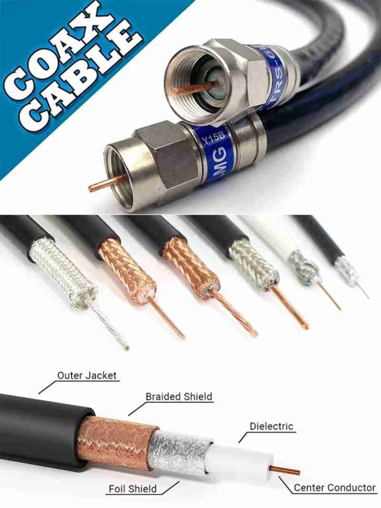
A coaxial cable is a specialized electrical cable consisting of a central conductor, dielectric insulator, shielding layer, and outer jacket. Its concentric structure allows RF, video, and data signals to travel with minimal interference and signal loss. Coax cables are used in TV systems, antennas, RF communication, CCTV, broadband internet, medical imaging, and aerospace electronics. Their main advantages include excellent EMI resistance and stable high-frequency performance.

Picture this: in 2024, a medical device manufacturer contacted Sino-Conn because their imaging system kept experiencing noise and distorted signals. The root cause wasn’t the sensor—it was the poor-shielding consumer-grade coax cables installed inside the device. After migrating to Sino-Conn’s precision micro-coax assemblies with controlled impedance and tri-layer shielding, the device’s image clarity improved instantly. This story reveals a powerful truth—choosing the right coax cable is crucial for any system that relies on clean, uninterrupted signal transmission.

Let’s dive deeper into how coaxial cables are structured, how they work, and how you can choose the correct type for your application.
What Is a Coaxial Cable and How Does It Work?
A coaxial cable is a concentric cable composed of a central conductor, dielectric layer, metallic shield, and protective jacket. It works by guiding high-frequency electrical signals through the center conductor while the shield blocks external electromagnetic interference. This coaxial structure ensures stable impedance, low noise, and reliable long-distance transmission for RF, video, broadband, and measurement applications.
Understanding How Coaxial Cables Work
Coaxial cables function based on fundamental electromagnetic principles. By placing the conductor and shielding in a concentric alignment, the cable controls how electrical energy travels, how fields propagate, and how interference is suppressed. This makes coaxial cables incredibly stable for high-frequency applications where other cable types would suffer severe losses.
What Is the Core Structure of a Coax Cable?
A coax cable includes four essential layers:
- Center Conductor – Carries the RF or data signal (materials: copper, tinned copper, silver plating, CCS).
- Dielectric Insulation – Maintains spacing and impedance (materials: PE, FPE, PTFE, foam dielectric).
- Shielding Layer – Protects against EMI (foil, braid, or multi-layer shielding).
- Outer Jacket – Adds protection and flexibility (PVC, PE, LSZH, TPU).
Each layer affects impedance, durability, frequency range, and bend performance.
Why Is It Called a “Coaxial” Cable?
The word coaxial refers to the fact that the conductor and shield share the same axis. This shared axis creates:
- controlled impedance
- uniform propagation characteristics
- minimal signal leakage
- strong EMI resistance
This structural benefit is what differentiates coaxial cables from twisted pair or parallel cable designs.
How Does a Coaxial Cable Transmit Signals?
Signals in a coax cable travel as electromagnetic waves between the conductor and shield, not inside the conductor itself. The dielectric controls wave velocity and impedance, while the shield confines the field, preventing interference.
Higher-quality dielectric materials (like PTFE or foam PE) allow signals to travel faster with less loss, which is critical for medical imaging, 5G antennas, and aerospace RF systems.
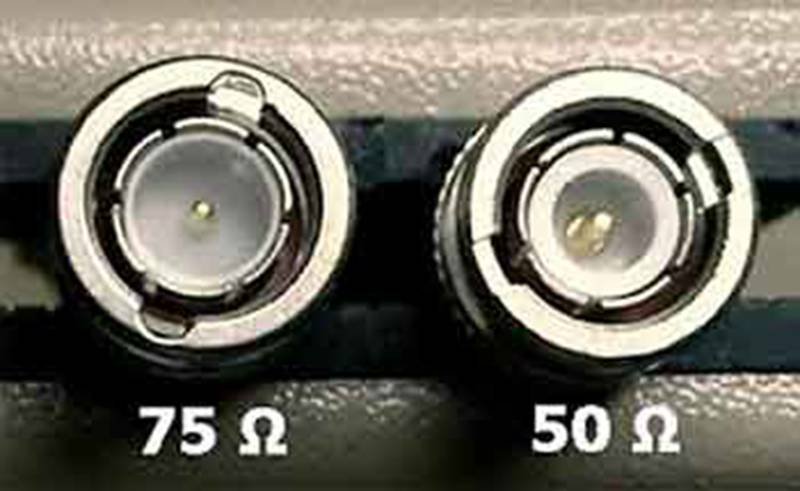
Why Is Impedance Important (50 Ohm vs 75 Ohm)?
| Impedance | Application Strength | Typical Uses |
|---|---|---|
| 50 Ω | Power handling & RF transmission | Radios, antennas, WiFi, military RF |
| 75 Ω | Low-loss video & data | TV, CCTV, satellite, broadband |
A mismatch in impedance can cause:
- signal reflection
- loss of amplitude
- degraded frequency response
Engineers must always match coax impedance with the system design.
What Is the Main Advantage of Coaxial Cable?
The biggest advantage is excellent EMI resistance and stable high-frequency transmission. This makes coax ideal for environments with heavy electrical noise or long cable lengths.
Secondary advantages include:
- predictable impedance
- strong mechanical durability
- compatibility with RF connectors
- long service life
What Are the Disadvantages of Coaxial Cable?
Despite its benefits, coax has limitations:
- bulkier than twisted pair
- less flexible than micro-cables
- requires specific connectors and tools
- higher cost for long runs compared to Ethernet
- limited data transmission speed vs fiber or Cat6/Cat7 Ethernet
Still, for RF and high-frequency analog transmission, coax remains unmatched.
Which Types of Coaxial Cables Are Used Today?
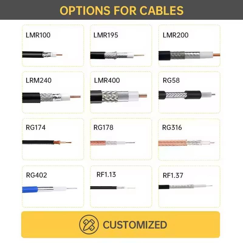
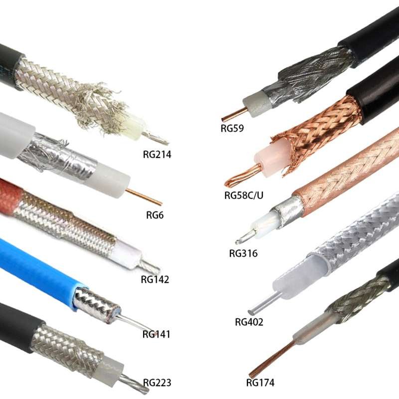
Modern coaxial cables include RG-series cables (such as RG6, RG59, RG58, RG174, RG316), low-loss cables (LMR series), micro-coax cables (AWG36–50), and semi-rigid or conformable RF cables used for high-frequency and mission-critical applications. Each type differs in impedance, attenuation, shielding, flexibility, and frequency performance, allowing engineers to select the right cable for video, telecom, RF, medical imaging, aerospace, automotive radar, or industrial instrumentation.
A Comprehensive Guide to Today’s Coaxial Cable Types
Modern coaxial cable varieties are designed to serve very different electrical and mechanical environments. Understanding the distinctions is crucial for RF engineers, OEMs, medical device designers, and installers selecting the right cable for performance, durability, and compliance.
Below is a fully structured guide of the most widely used categories.
1. RG-Series Coaxial Cables (Most Common & Widely Used)
RG (Radio Guide) cables are the most recognized category, covering a wide range of diameters, impedances, and applications.
Common RG Cables and Their Use Cases
| Cable Type | Impedance | Diameter | Frequency Range | Typical Applications |
|---|---|---|---|---|
| RG6 | 75Ω | 6.9–7.0 mm | Up to 3 GHz | TV, satellite, broadband |
| RG59 | 75Ω | 6.1 mm | Up to 1 GHz | Analog CCTV, short video |
| RG58 | 50Ω | 4.9–5.0 mm | Up to 1 GHz | Radio, WiFi, RF modules |
| RG174 | 50Ω | 2.5 mm | Up to 2–3 GHz | GPS, IoT, antennas |
| RG316 | 50Ω | 2.5 mm | Up to 6 GHz | High-frequency RF, aerospace |
RG cables vary in flexibility, jacket material, and shielding level. They remain the standard for telecom installers, RF test engineers, and consumer electronics.
2. Low-Loss Coaxial Cables (LMR Series)
Low-loss coax cables like the LMR series outperform standard RG cables by reducing attenuation through:
- Foamed PE or advanced dielectric
- High-density braid
- Multi-layer foil shields
Why Low-Loss Coax Is Important
At high frequencies (2–6 GHz), signal attenuation becomes significant. Low-loss options maintain:
- Higher signal strength
- Better VSWR
- Longer usable distances
Typical LMR Models
| Model | Attenuation | Key Use Cases |
|---|---|---|
| LMR-200 | Low | WLAN, GPS, mobile antennas |
| LMR-240 | Lower | Long-distance antenna feeds |
| LMR-400 | Very low | Base stations, outdoor RF |
| LMR-600 | Ultra low | Telecom tower infrastructure |
Sino-Conn commonly manufactures custom LMR assemblies with N-type, SMA, RP-SMA, TNC, UHF, BNC, and proprietary RF connectors.
3. Semi-Rigid and Semi-Flexible (Conformable) Coax
Used for aerospace, defense, precision instruments, and microwave systems.
Semi-Rigid Coax
- Copper or aluminum outer tube
- Holds its shape once bent
- Extremely low loss and excellent shielding
- Supports microwave frequencies (18–40 GHz+)
Typical models: 0.086”, 0.141”, 0.250” OD coax.
Semi-Flexible / Conformable Coax
- Similar performance to semi-rigid
- Can be hand-formed without tools
- Used when routing space is limited
Applications include radar modules, satellite RF feeds, medical imaging arrays, and defense electronics.
4. Micro-Coax & Ultra-Fine Coax (AWG36–50)
These cables are essential for high-density electronic and medical systems requiring signal integrity at tiny diameters.
Applications
- Ultrasound probes
- Endoscopes
- Wearable medical sensors
- Miniature antennas
- Aerospace instrumentation
- Compact IoT devices
Why Micro-Coax Is Important
- Extremely tight impedance control
- Individual shielding per channel
- Flexibility for repeated bending
- High signal-to-noise ratio for microvolt-level signals
Sino-Conn produces micro-coax bundles and multi-lumen medical cable assemblies, often with 64–256 individually shielded channels.
5. Tri-Shield, Quad-Shield & High-EMI Coaxial Cables
In industrial or outdoor environments with heavy interference, enhanced shielding is essential.
Shielding Levels
| Type | Shield Layers | Use Case |
|---|---|---|
| Dual Shield | Foil + Braid | Home A/V |
| Tri-Shield | Foil + Braid + Foil | Urban noise environments |
| Quad Shield | Foil + Braid + Foil + Braid | Industrial, long-distance cables |
Quad-shielded versions dramatically improve SNR (Signal-to-Noise Ratio) and prevent RF leakage.
6. Specialty Coax: Low-Noise, High-Temp, LSZH, Mil-Spec
Some projects require specialized coatings or performance characteristics.
Low-Noise Coax
Used in:
- Precision measurement
- Medical sensors
- Seismology
Reduces microphonic noise caused by cable vibration.
High-Temperature Coax
With FEP, PTFE, PFA jackets, withstands:
- Chemical exposure
- High heat (up to 200–260°C)
- UV radiation
LSZH (Low Smoke Zero Halogen) Coax
Used in:
- Hospitals
- Rail systems
- Public buildings
Meets strict fire safety standards.
Mil-Spec Coax
Examples: MIL-DTL-17 compliant cables used in:
- Military radios
- Aerospace
- Satellites
Which Coax Cable Should You Choose?
| Application | Recommended Cable |
|---|---|
| TV & satellite | RG6 |
| CCTV | RG59 |
| WiFi/GPS antennas | RG174 / RG316 |
| Telecom towers | LMR400 / LMR600 |
| Medical imaging | Micro-coax (AWG38–50) |
| Aerospace | Semi-rigid / Mil-spec |
| Industrial EMI-heavy zones | Quad-shielded RG6 / RG11 |
| High-frequency RF testing | RG316, semi-rigid |
What Are the Key Components and Materials of a Coax Cable?
A coaxial cable is composed of a center conductor, dielectric insulation, metallic shielding, and an outer protective jacket. Each layer uses specific materials—such as copper, aluminum, PTFE, PE, foil, braid, PVC, LSZH, or TPU—to control impedance, flexibility, temperature resistance, and EMI protection. The choice of materials directly affects cable durability, signal loss, flexibility, and lifespan in different environments.
The material composition of a coax cable determines its electrical characteristics, durability, bend performance, and environmental resistance. Engineers choosing coax for professional applications—RF systems, medical imaging, industrial sensors, aerospace, automotive ADAS—must understand how each layer’s material influences performance and longevity.
What Materials Are Used for Conductors, Dielectrics, and Shields?
Center Conductors
- Solid copper – Highest conductivity, premium RF
- Copper-clad steel (CCS) – Strong pulling strength, used for TV cables
- Tinned copper – Corrosion-resistant, easier soldering
- Silver-plated copper – High-frequency aerospace & medical applications
Dielectric Materials
- Polyethylene (PE) – Common, low-loss
- Foam PE – Even lower loss, best for long-distance video
- PTFE (Teflon) – High-temperature, extreme stability
- FEP – Chemical-resistant
The dielectric determines impedance and signal velocity factor.
Which Shielding Methods Reduce EMI (Braid, Foil, Quad-Shield)?
Shielding is the heart of coaxial performance.
| Shield Type | EMI Protection | Flexibility | Typical Use |
|---|---|---|---|
| Foil | Good | Fair | Broadband, CATV |
| Braided copper | Very good | Very flexible | RF, antennas |
| Dual shield | Excellent | Moderate | CCTV, satellite |
| Quad shield | Superior | Stiffer | High-interference environments |
For medical micro-coax (used in ultrasound probes), individual shielding is applied to each conductor, resulting in 128–512 individually shielded micro-channels.
How Does Jacket Material Affect Temperature, Flexibility, and Durability?
Jacket selection affects:
- UV resistance
- Oil resistance
- Abrasion durability
- Temperature range
- Flexibility & bend radius
Common Jacket Types
- PVC – Cost-effective, flexible
- PE – Outdoor, UV-resistant
- LSZH – Fire-safe buildings & hospitals
- TPU – High-flex industrial/medical use
- FEP/PTFE – Harsh chemical or high-heat environments
For longevity outdoors, PE is preferred; for high-flex robotics, TPU is ideal.
What Factors Influence Coax Cable Longevity and Degradation?
Coax lifespan depends on:
- Material quality
- Water resistance
- Shielding integrity
- Repeated bending
- Heat exposure
- Connector termination quality
A poorly installed connector can reduce cable lifespan by 40–60%, especially in high-frequency applications.
Sino-Conn’s manufacturing process—triple inspection, controlled shielding density, precision crimping—helps ensure maximum durability.
How Are Coaxial Cables Manufactured and Tested?
Coaxial cables are manufactured through a controlled multi-stage process that includes conductor drawing, dielectric extrusion, shielding application, jacketing, and final assembly into custom lengths. They are then tested for impedance, attenuation, capacitance, shielding effectiveness, VSWR, continuity, and environmental resistance. Strict quality control ensures each cable meets electrical, mechanical, and safety standards required for telecom, RF, medical, aerospace, and industrial applications.

Coaxial cable manufacturing is a precision-driven process that requires tight control over concentricity, dielectric quality, shielding density, and impedance. Every step can influence RF performance, signal loss, and the cable’s long-term reliability. Below is a detailed, end-to-end engineering process used by high-quality coaxial cable manufacturers—including Sino-Conn and global telecom suppliers.
1. Conductor Production — Copper Rod → Fine Conductor Wire
The manufacturing process begins with continuous copper rod breakdown, where large copper rods are drawn into thinner conductors.
Key Steps
- Rod breakdown drawing reduces a thick copper rod into controlled AWG sizes.
- Annealing restores flexibility and conductivity.
- Plating options include bare copper, tinned copper, silver plating (for high-frequency), or SPC/SCC.
Why This Matters
Conductor smoothness directly affects skin effect, high-frequency attenuation, and signal phase stability—critical for RF communication and medical imaging cables.
2. Dielectric Extrusion — Achieving Perfect Concentricity
The conductor is fed into an extrusion line where a dielectric layer (PE, FPE foam, PTFE, or low-loss material) is applied.
Critical Control Parameters
- Concentricity tolerance (±0.02–0.05 mm)
- Dielectric density for impedance tuning
- Foaming ratio (for low-loss cables)
- Surface smoothness for stable shielding adhesion
Why This Matters
Dielectric quality determines:
- 50Ω or 75Ω impedance accuracy
- Cable attenuation
- VSWR stability
- High-frequency performance
Poor dielectric uniformity causes return loss problems and signal reflections.
3. Shielding Application — Braid and Foil Layers
Coaxial cables use one or multiple layers of shielding to prevent EMI and signal leakage.
Shield Types
- Aluminum foil + polyester tape (100% coverage)
- Braid shielding (16–95% coverage)
- Quad-shield (foil + braid + foil + braid)
Shielding Machinery
- High-speed braiders
- Servo-controlled bobbins
- Uniform strand tension systems
Why This Matters
Shield integrity directly affects:
- Shielding effectiveness (dB)
- Signal-to-noise ratio
- Leakage current performance
- Compliance with FCC/CE RF emission limits
4. Outer Jacket Extrusion — Mechanical & Environmental Protection
The shielded core passes through another extrusion line to apply the jacket.
Jacket Materials
- PVC (general use)
- PE (outdoor, UV-resistant)
- FEP/PTFE (high-temperature, aerospace)
- LSZH (low smoke, zero halogen for hospitals & transit)
Environmental Ratings
- UV resistance
- Flame rating (UL94V-0, VW-1)
- Oil resistance (UL OIL RES I/II)
- Temperature: –40°C to 105–260°C
5. Cable Assembly — Cutting, Connectorization, Crimping
After cable production, coax is cut, stripped, and assembled into finished cable assemblies.
Assembly Processes
- Precision stripping (multi-stage stripping machines)
- Crimping or soldering connectors (SMA, N, BNC, TNC, RP-SMA, F-type, MCX/MMCX)
- Injection molding or overmolding for strain relief
- Heat-shrink tubing sealing
Why Assembly Accuracy Matters
Incorrect strip lengths, braid folding, or impedance mismatches lead to:
- High VSWR
- Frequency drop-off
- Intermittent signal loss
TESTING & VALIDATION — How Coaxial Cables Are Verified Before Shipment
Top manufacturers like Sino-Conn test 100% of cables, not random batches. Testing includes electrical, mechanical, environmental, and safety evaluations.
6. Electrical Testing — High-Frequency Performance Validation
Required Tests
| Test | Purpose |
|---|---|
| Impedance test (50/75Ω) | Ensures return-loss stability |
| Attenuation test | Confirms low-loss performance |
| Capacitance/Inductance | Verifies dielectric consistency |
| VSWR (Voltage Standing Wave Ratio) | Detects mismatched termination |
| Shielding effectiveness (dB) | Confirms EMI protection level |
| Continuity & short-circuit | Ensures correct conductor paths |
Equipment Used
- Network analyzers (1–40 GHz)
- Time-domain reflectometers (TDR)
- RF signal generators

7. Mechanical Testing — Durability & Wear Resistance
Testing ensures the cable withstands bending, vibration, and physical stress.
Mechanical Tests
- Flex/Bend test (up to 10,000+ cycles)
- Pull force test (connector retention)
- Concentricity measurement
- Abrasion resistance
- Crimp tensile test
8. Environmental Testing — Safety & Long-Term Reliability
Used in medical, aerospace, telecom, and military projects.
Environmental Tests
- Temperature cycling (–40°C to +150°C)
- Salt spray (corrosion resistance)
- UV exposure
- Oil/chemical resistance
- Fire/flame propagation test
- Aging test
9. Compliance Testing — UL, ISO, ROHS, REACH, MIL-STD
Sino-Conn supports certifications such as:
- UL AWM styles
- ISO9001, ISO13485 (medical)
- RoHS / REACH / PFAS compliance
- MIL-DTL-17 (military coax standard)
What Devices and Industries Depend on Coaxial Cables?
Coaxial cables are used in communication systems, broadcast equipment, satellite receivers, medical imaging devices, aerospace systems, military radios, surveillance networks, and commercial RF applications. Their shielding effectiveness, stable impedance, and low-loss transmission make them essential anywhere high-frequency or noise-sensitive signals must be carried reliably over distance.
Coaxial cable technology may date back nearly a century, but it remains indispensable because no other cable design balances EMI immunity, controlled impedance, mechanical durability, and high-frequency performance as effectively. Many industries still prefer coax cables even as fiber optics and Ethernet grow because coax handles RF signals, analog transmission, and shielded high-bandwidth workflows in ways alternatives cannot replace.
Below is an in-depth look at the major devices and sectors that rely on coaxial cables today.
1. Telecom & Broadband Systems — CATV, Internet, and RF Transmission
Telecommunications remains the largest consumer of coaxial infrastructure.
Major Device Types
- Cable modems (DOCSIS systems)
- Home broadband coax networks
- CATV set-top boxes
- TV antennas and distribution amplifiers
- RF signal amplifiers
- Base station RF feeders
Why Coax Is Critical
Coaxial cables provide:
- Stable 75Ω impedance for broadcast & CATV
- Low-loss performance over long distances
- Superb EMI shielding in dense urban networks
- Cost-effective installation and maintenance
2. Satellite Communication Systems — Residential & Commercial
Satellite TV, GPS antennas, and VSAT systems depend heavily on coax cables due to their frequency range (up to 3–6 GHz or higher).
Devices Using Coax
- LNB (Low Noise Block) connections
- Satellite receivers (DVB-S, DVB-S2)
- GPS antennas (active/passive)
- Dish alignment equipment
Why Coax Works Well
- Maintains signal integrity over long cable runs
- Handles high-frequency microwave bands
- Protects weak signals from external interference
3. Medical Devices & Healthcare Systems — Imaging, Monitoring, Diagnostics
Hospitals increasingly rely on shielded, sterile, and biocompatible coaxial assemblies.
Applications
- Ultrasound probes
- ECG/EEG signal lines
- Defibrillator shock cables
- X-ray signal transfer
- Endoscopy camera feeds
- Imaging detector arrays
- Non-invasive monitoring sensors
Why Medical Devices Require Coax
- Ultra-low noise transmission
- Stable impedance supporting sensitive sensors
- High flexibility for handheld probes
- Options for biocompatible & sterilizable jackets (TPU, silicone)
- EMI shielding around life-critical systems
4. Aerospace & Defense — High-Reliability RF & Radar Systems
Aerospace and defense environments demand cable durability far beyond consumer-grade standards.
Use Cases
- Aircraft communication antennas
- Radar systems (X-band, Ku-band)
- UAV telemetry & control
- Military radios (HF/VHF/UHF)
- Missile guidance assemblies
- Cockpit instrument clusters
Required Characteristics
- Extreme temperature resistance (–55°C to 200°C+)
- Low-loss PTFE/FEP dielectrics
- High shielding effectiveness (90–120 dB)
- MIL-DTL-17 compliance
5. Automotive & Transportation — Radar, Cameras, Infotainment
Modern vehicles rely on coax for both high-frequency and shield-sensitive applications.
Automotive Applications
- ADAS radar sensors (24 GHz, 77 GHz)
- Backup cameras & dashboard video
- Automotive Ethernet via coax (CoaXPress, FPD-Link)
- GPS antennas
- Infotainment modules
Why Automotive Systems Prefer Coax
- Vibration-resistant construction
- Smaller OD for routing in tight spaces
- High EMI immunity in engine bay environments
- Lightweight vs. twisted-pair alternatives
6. Broadcasting, Audio & Professional Video Equipment
Even with HDMI and SDI dominating video transport, coax remains central to broadcast infrastructure.
Devices Using Coax
- Studio cameras
- Microphones and audio mixers (RF sections)
- RF in-ear monitors
- SDI video systems (75Ω coax)
- RF transmission towers
- Wireless microphone receivers
Why Broadcasters Still Use Coax
- Superior analog signal integrity
- Low jitter for digital SDI systems
- Durable, field-serviceable connectors (BNC, TNC)
7. Industrial, Test & Measurement Applications
Factories and engineering labs rely heavily on coaxial assemblies.
Applications
- Oscilloscopes & signal analyzers
- RF test benches
- VNA calibration kits
- Sensors requiring shielded analog transmission
- Machine vision systems (via CoaXPress)
Why Industrial Environments Prefer Coax
- Tolerance for harsh EMI
- Consistent impedance for measurement accuracy
- Durable braided shields for vibration areas
8. IoT, Smart Devices & Consumer Electronics
The rise of IoT brought coax back into the spotlight.
Devices Using Coax
- Wi-Fi antennas
- Zigbee & LoRa modules
- Security cameras
- Routers & access points
- Smart home hubs
Key Benefits
- Strong RF stability
- Low insertion loss
- Compact routing in embedded devices
How Do You Choose the Right Coax Cable for Your Application?
Choosing the right coax cable requires evaluating impedance (50Ω or 75Ω), frequency range, attenuation, shielding level, bend radius, environmental conditions, and connector compatibility. Applications using RF signals typically require 50Ω cables, while video and broadcast systems use 75Ω. Factors like jacket material, dielectric type, and cable diameter also determine performance and durability.
Selecting coax cable is not as simple as matching a model number. Engineers must consider electrical, mechanical, and environmental requirements—especially for medical, industrial, and military-grade applications.
Here is a full decision-making framework used by professional RF and system engineers.
Start With Impedance: 50Ω vs 75Ω
| Impedance | Use Case | Examples |
|---|---|---|
| 50Ω | RF communication, antennas, transmitters, test equipment | RG58, RG174, RG316 |
| 75Ω | Video, broadcast, high-frequency data | RG6, RG59 |
The wrong impedance leads to reflections, high VSWR, and signal loss.
Match the Cable to Your Frequency Range
High-frequency applications require cables with:
- Lower-loss dielectrics
- Tighter impedance tolerance
- High-density shielding
Example:
- RG174 works for GPS/WiFi (1–2GHz)
- RG316 works for 5–6GHz
- Low-noise micro-coax is used in 20–40MHz ultrasound probes
The higher the frequency, the more sensitive the system becomes to manufacturing tolerances.
Evaluate Shielding Based on EMI Levels
| EMI Environment | Recommended Shielding |
|---|---|
| Light indoor | Single braid |
| Industrial floor | Foil + braid |
| Military/aerospace | Quad shield or silver-plated braid |
| Medical imaging | Individually shielded micro-coax |
Shielding prevents cross-talk, interference, and data corruption.
Select Jacket Material Based on Environment
| Environment | Jacket Material |
|---|---|
| Indoor electronics | PVC |
| Outdoor long-term | PE |
| High-flex robotics | TPU |
| High-temperature | PTFE or FEP |
| Hospital and public buildings | LSZH |
The wrong jacket can lead to cracking, moisture damage, or RF leakage.
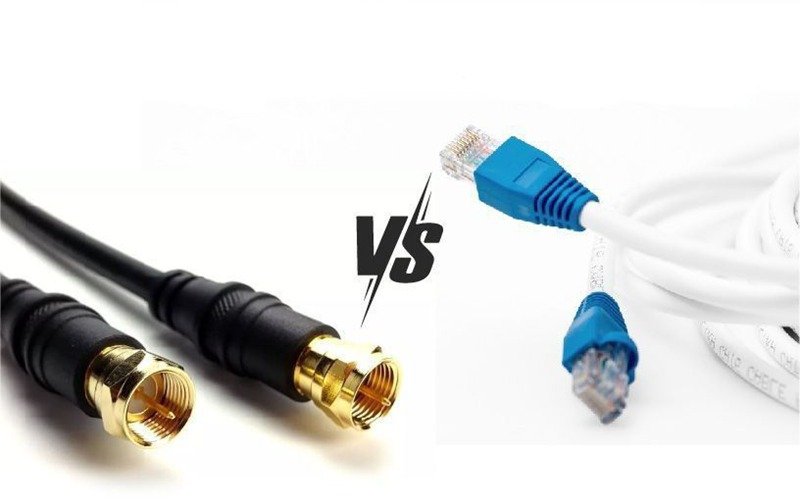
How Does Coax Compare to Ethernet? Which Is Better?
This is a common question engineers ask.
Coax vs Ethernet — Comparison Table
| Feature | Coax Cable | Ethernet Cable |
|---|---|---|
| RF Frequency Support | Excellent | Poor |
| EMI Resistance | High | Medium |
| Distance Without Repeaters | Longer (up to 500m) | Shorter |
| Flexibility | Higher | Medium |
| Data Speed | Lower (unless MoCA) | Faster |
| RF Applications | Best choice | Not suitable |
Which Is Better?
Neither is categorically “better”—they serve different purposes.
- Coax is better for RF, antennas, CCTV, satellite, and high-noise environments.
- Ethernet is better for IP data, networking, and computer communication.
Conclusion
Choosing the right coaxial cable assembly partner is not just about buying a cable—it is about securing signal stability, long-term product reliability, and an engineering team that understands your application as deeply as you do. Sino-conn has become a trusted partner for OEMs, research teams, medical device companies, telecom integrators, and RF system manufacturers because we combine technical precision, fast engineering support, and flexible customization in a way few suppliers can match.
At Sino-conn, every coax cable assembly—whether RG-type, low-loss, micro-coax, RF jumper, or high-frequency SMA/MCX/MMCX harness—is engineered according to your exact requirements: impedance, shielding level, dielectric type, operating frequency, bending radius, flammability rating, OD constraints, and connector compatibility. Our team provides accurate drawings within 30 minutes, supports NO MOQ, and delivers rapid samples in as fast as 2–3 days. For urgent programs, mass production can ship in under 2 weeks, helping OEMs avoid delays in development cycles or market launches.
Our manufacturing process follows strict quality control with 100% full inspection—including continuity tests, impedance verification, shielding effectiveness checks, VSWR measurement, and visual + mechanical QC. With certifications such as UL, ISO, RoHS, REACH, PFAS, COC, and COO, Sino-conn ensures your assemblies align with global compliance standards across telecom, medical, aerospace, automotive, and industrial markets.
If you’re developing new equipment, optimizing an existing design, or scaling production and need a dependable coaxial cable assembly partner, Sino-conn is ready to support you from concept to mass manufacturing.
Contact Sino-conn now to request drawings, specifications, pricing, or a custom-engineered coaxial assembly solution.
Our engineers are available for video calls, technical consultation, and rapid prototyping—so your project can move forward without delays.


