 Skip to content
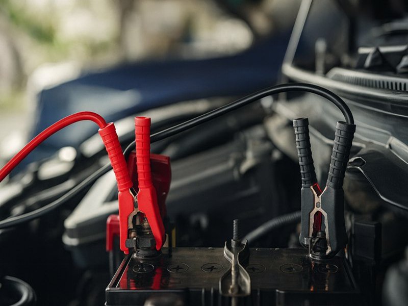
When your car refuses to start and you turn the key only to hear a click or silence, panic often sets in. But in many cases, the solution is simple: a safe and proper jump-start using jumper cables. Yet countless drivers — even experienced ones — connect cables in the wrong order, skip safety checks, or use poor-quality cables that overheat or fail when needed most. What should be a quick rescue can turn into sparks, ECU damage, or a hazardous situation under the hood.
Before we dive deeper, here is the essential answer many search for — fast and clear:
To safely connect jumper cables, attach the red clamp to the dead battery’s positive terminal, then connect the other red clamp to the donor battery’s positive terminal. Next, attach the black clamp to the donor battery’s negative terminal and place the final black clamp on an unpainted metal ground of the dead vehicle. Start the donor car, wait a few minutes, then start the dead car. Remove cables in reverse order.
It sounds simple — and it is — but behind this four-step sequence lies the entire reason jump-starting works. The correct order avoids sparks, reduces battery stress, and protects vehicle electronics from voltage spikes. And if you’ve ever stood on a cold roadside with a dead battery, you know how much confidence and clarity matter in moments like these.
Speaking of moments: imagine you’re stuck in a deserted parking lot after a long day. Another driver offers help, but neither of you is fully sure which clamp goes where. You guess — and a small spark flashes. It’s harmless this time, but what if the next mistake isn’t? Knowing the correct method doesn’t just get your engine running; it protects both vehicles, and more importantly you.
This guide walks you through exactly how jumper cables work, which order to connect them, what to avoid, and how proper battery cables — including custom-spec options like Sino-conn’s — make a major difference in performance and safety. Whether you’re a regular car owner or a professional working with automotive or industrial power systems, you’ll find deeper insights throughout this article.
What Are Jumper Cables and How Do They Work?
Jumper cables are heavy-gauge power cables used to transfer current from a charged battery to a dead one. They consist of thick copper or copper-clad wires, insulated jackets, and spring-loaded clamps that attach to the battery terminals. When connected in the correct order, they allow the donor vehicle’s battery to supply the voltage needed for the disabled vehicle to start. Their effectiveness depends on conductor thickness, material quality, and the strength of the clamps.
Understanding the Mechanics Behind Jumper Cables
Jumper cables look simple, but they play a critical electrical role. They must safely carry high current (200–600 amps) within a short burst while minimizing voltage drop and preventing overheating. To do this effectively, their construction — conductor choice, gauge, insulation, and clamp quality — becomes far more important than most consumers realize. Poorly made jumper cables lead to melted insulation, reduced conductivity, and failed jump-starts, especially in cold conditions or with larger engines that require higher starting currents.
Beneath the insulation, jumper cables rely on a principle of basic electrical transfer: providing enough amperage from the donor battery to turn the starter motor of the dead vehicle. The better the cable, the more efficiently that amperage travels. This is why aftermarket cables vary dramatically — from ultra-thin budget options to industrial-grade wiring similar to Sino-conn’s custom battery cable assemblies.
A holistic understanding of jumper cables requires examining conductor design, insulation durability, clamp mechanics, and real-world scenarios. Cars with larger engines, diesel trucks, or vehicles operating in low temperatures all require sturdier cables. Meanwhile, EVs and hybrids introduce a different set of considerations for safety. In this section, we break down each cable component and its impact on real performance.
Below, you’ll find a detailed technical breakdown of cable structure and performance—helpful for both everyday drivers and OEM engineers designing equipment relying on high-current battery cables.
What Is Inside a Jumper Cable?

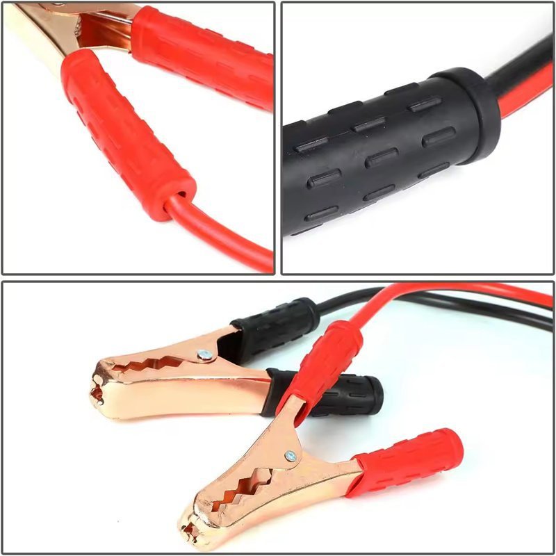
The internal anatomy of a jumper cable determines how well it can carry current under heavy load. High-quality cables use pure copper conductors, which offer superior conductivity and handle higher currents with minimal resistance. Copper-clad aluminum (CCA) cables are cheaper and lighter but lose efficiency under stress.
The insulation must withstand heat, abrasion, and bending. Materials such as PVC, rubber, and TPE are common, but rubber remains the most flexible in cold weather. clamps use steel or copper-plated materials; the teeth and spring tension directly affect surface contact and therefore how easily current flows.
| Component | Better Quality Option | Lower Quality Option | Impact on Performance |
|---|---|---|---|
| Conductor | Pure copper | Copper-clad aluminum | Lower resistance, faster starts |
| Gauge | 2–4 AWG | 8–10 AWG | Thicker gauge handles high current |
| Insulation | Rubber/TPE | Hard PVC | Flexibility in cold, durability |
| Clamps | Copper-plated heavy-duty | Thin steel clamps | Better terminal grip, safer use |
| Length | 12–20 ft | <10 ft | Easier vehicle positioning |
The higher each specification, the safer and more reliable the jump-start.
Which Gauge and Length Matter Most?
Gauge is the backbone of jumper cable performance. Thicker cables (lower AWG numbers) carry more current with less voltage drop. A 2-gauge cable can deliver high amperage quickly, crucial for SUVs, trucks, and vehicles in cold climates. Standard cars can often manage with 4- or 6-gauge cables, but thin 8- or 10-gauge cables commonly sold in convenience stores are insufficient for many vehicles.
Length influences usability. A 12–20 ft cable allows flexible vehicle positioning without exceeding practical limits. Excessively long cables can cause significant voltage loss, resulting in weaker starting performance.
Are Heavy-Duty Battery Cables Safer for Jump-Starting?
Yes — especially for large engines, commercial vehicles, or cold environments. Heavy-duty cables reduce heat buildup, lower resistance, and ensure consistent power transfer. They are also more durable, resist cracking, and maintain flexibility even at subzero temperatures.
This is why many OEMs, fleet operators, and engineering teams prefer using industrial-grade or custom-made battery cables. Companies like Sino-conn manufacture cables that match exact current requirements, withstand extreme operating conditions, and comply with UL, ISO, ROHS, and other certifications — essential for high-reliability electrical systems.
What Should You Check Before Connecting Jumper Cables?
Before connecting jumper cables, check that both vehicles use the same voltage, usually 12V, and ensure both ignitions are off. Inspect the batteries for cracks, leaks, swelling, or corrosion. Confirm the clamps and cable insulation are intact and the vehicles are safely parked with parking brakes engaged. Only jump-start if the battery is physically safe and the electrical system shows no severe faults. These steps reduce risk of sparks, short circuits, and damage to vehicle electronics.
The Critical Safety Checks Before You Attach Any Cable
Before touching a single clamp, the most important part of a safe jump-start happens before the cables are connected. Many accidents occur not because the jump-starting process is complicated but because drivers skip crucial safety checks that would have warned them of electrical hazards, battery failures, or incompatible systems. A jumper cable can transfer several hundred amps instantaneously—enough power to weld metal or destroy electronics if misused. That’s why understanding what to check ahead of time is essential.
First, verifying voltage compatibility prevents damage to alternators, ECUs, and electronics. Jumping from a 12V vehicle to a 24V system—or vice versa—can instantly overload the recipient’s electrical components. Second, examining the physical condition of the battery is not optional; a cracked or swollen battery can explode under a sudden current surge. Third, safe vehicle positioning and the environment around you matter more than most people realize. Jump-starting in wet or unstable conditions increases risk significantly.
These checks are not just for casual drivers. Professional mechanics, fleet operators, and engineers know that a battery can appear “dead” but actually be suffering from internal shorting, freezing, or cell rupture. Every jump-start is a risk if done blindly. Below we break down the key factors to inspect, why they matter, and what professionals always do before attaching clamps.
A table is included further below summarizing risks and recommended actions, helpful for both everyday users and OEM teams who work extensively with battery cable assemblies.
Do the Cars Need to Match Voltage?
Yes — voltage compatibility is the first non-negotiable rule. Most passenger vehicles use 12-volt systems, but some diesel trucks, commercial equipment, and older machinery may use 24-volt batteries. Jumping a 12V vehicle with a 24V source can instantly fry sensitive electronics, blow fuses, overload the alternator, or permanently damage the ECU.
Hybrid vehicles also bring special considerations: they use a high-voltage drive battery and a small auxiliary 12V battery. Jump-starting hybrids must be done on the correct terminals indicated by the manufacturer.
If you’re not certain of the voltage, check:
- Battery label
- Vehicle manual
- Under-hood voltage markings
Voltage mismatch is one of the most common causes of catastrophic electrical damage during amateur jump-starts.
What Conditions Should You Check Before Connecting Cables?
Before attaching any clamp, make sure:
- Both vehicles are turned off
- Parking brakes are engaged
- Transmissions are in Park or Neutral
- The area is dry and safe
- No moving engine components are nearby
Inspect the dead battery’s terminals for corrosion, rust, or loose connections. If corrosion is present, gently remove it with a brush or cloth before attaching clamps, as poor contact creates heat and sparks.
Check the cable insulation for cuts or exposed wires. Damaged insulation can create short circuits when current flows. Confirm clamps still have tension; loose clamps can slip, causing arcing.
These checks are quick, but skipping them dramatically increases risk.
When Should You Avoid Using Jumper Cables?
Never attempt a jump-start if the battery is:
- Leaking
- Cracked
- Bloated or swollen
- Frozen
A frozen battery is especially dangerous. When a frozen battery receives sudden current, the internal ice expands rapidly and can cause the casing to rupture.
Avoid jump-starting if you smell sulfur or rotten eggs—a sign of internal battery failure. Also avoid jump-starting on:
- Steep hills
- Wet, flooded areas
- Places with flammable vapors
Additionally, if the vehicle presents major electrical issues (no lights, flickering dashboard, or repeated battery failures), a jump-start may not help and could worsen underlying faults.
Table: Key Safety Checks Before Jump-Starting
| Safety Check | Why It Matters | Risk If Ignored |
|---|---|---|
| Confirm 12V vs 24V | Prevents ECU/alternator overload | Severe electrical damage |
| Inspect battery casing | Identifies leaks, cracks, swelling | Explosion or acid leak |
| Check clamps & insulation | Ensures safe current transfer | Sparks, short circuits |
| Confirm vehicle gear & brake | Prevents movement during start | Vehicle roll or accident |
| Avoid frozen batteries | Prevents internal rupture | Battery explosion |
| Avoid strong sulfur smell | Indicates internal failure | Fire risk or battery rupture |
How to Connect Jumper Cables Step by Step
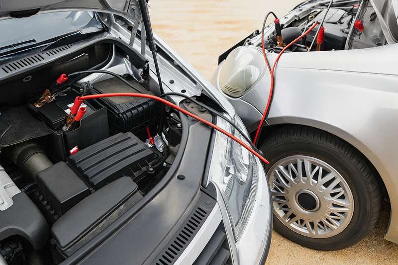
To connect jumper cables safely, park both vehicles close enough for the cables to reach, turn off both ignitions, and set parking brakes. First, attach the red clamp to the positive terminal of the dead battery, then to the positive terminal of the donor battery. Next, connect the black clamp to the donor battery’s negative terminal and the final black clamp to a metal ground on the dead vehicle. Start the donor vehicle, wait a few minutes, then start the dead vehicle and remove the cables in reverse order.
Step 1: Park the Vehicles and Prepare Safely
Position the two vehicles close enough for the cables to reach both batteries without stretching, but avoid the cars touching each other. Put both transmissions in Park (or Neutral for manuals), engage the parking brakes, and switch off all electrical loads such as lights, AC, and audio systems. Turn off both ignitions. Open the hoods and locate the batteries and their positive (+) and negative (–) terminals. Make sure the cable clamps and insulation look intact before proceeding.

Step 2: Connect the Positive (Red) Clamps
Begin with the positive side of the circuit. Attach the red clamp firmly to the positive (+) terminal of the dead battery, ensuring good metal contact. Then connect the other red clamp to the positive (+) terminal of the donor vehicle’s battery. By connecting positives first, you reduce the chance of accidental grounding and short circuits. Make sure the clamps are stable and not touching any moving parts or metal surfaces that could cause contact issues later.
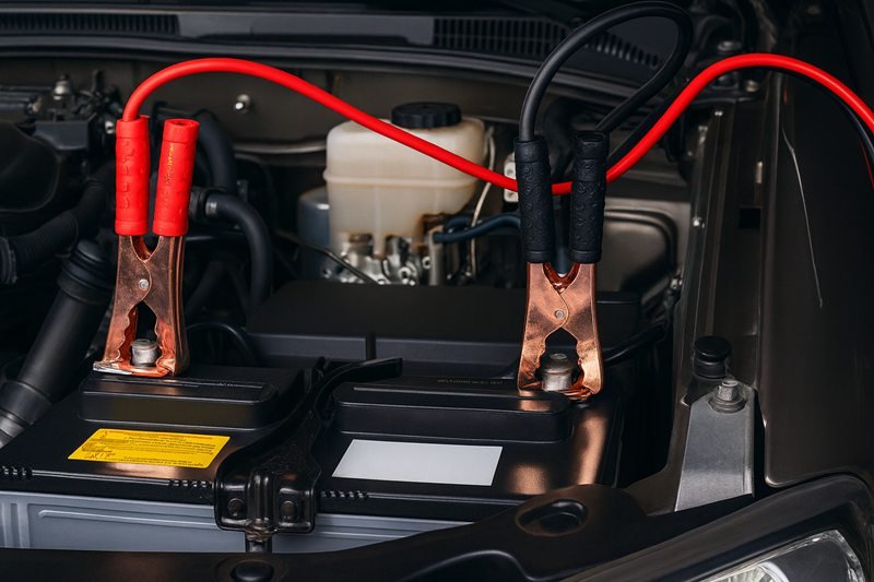
Step 3: Connect the Negative (Black) Clamps Correctly
Next, attach the black clamp to the negative (–) terminal of the donor battery. This completes the ground side on the donor vehicle. The final black clamp should not go on the dead battery’s negative terminal. Instead, connect it to a solid, unpainted metal point on the dead vehicle, such as an engine bracket or chassis ground. This keeps any potential spark away from the battery itself, where flammable gases might accumulate.
Step 4: Start the Donor Vehicle and Then the Dead Vehicle
With all clamps properly connected, start the donor vehicle first and let it idle for 2–5 minutes. This allows current to flow and gives the dead battery a surface charge. After a few minutes, try starting the dead vehicle. If it starts immediately, let both vehicles idle for a short time with the cables still connected. If it doesn’t start, wait another few minutes and try again. If the engine still won’t crank after two or three attempts, there may be a deeper battery or electrical issue.
Step 5: Remove the Cables in Reverse Order
Once the dead vehicle is running, it’s time to disconnect the cables—always in reverse order of how you connected them. First, remove the black clamp from the grounded metal point on the revived vehicle. Second, remove the black clamp from the donor battery’s negative terminal. Third, remove the red clamp from the donor battery’s positive terminal. Finally, remove the red clamp from the revived vehicle’s positive terminal. Make sure the clamps do not touch each other or any metal while they are still connected to a battery.
Step 6: Let the Revived Vehicle Recharge
After all cables are removed, keep the revived vehicle’s engine running for at least 15–20 minutes. Ideally, take the car for a short drive rather than letting it idle, so the alternator can charge the battery more effectively. Watch for warning lights on the dashboard, such as battery or alternator indicators. If the car struggles to start again later the same day, the battery may be nearing the end of its life or there may be a charging system problem that requires professional diagnosis.
Step-by-Step Summary Table
| Step | Action | Purpose |
|---|---|---|
| 1 | Park cars, turn off ignitions, set brakes | Ensure safety and stability |
| 2 | Red clamp → dead battery (+) | Start positive connection on dead side |
| 3 | Red clamp → donor battery (+) | Complete positive circuit |
| 4 | Black clamp → donor battery (–) | Establish donor ground |
| 5 | Black clamp → metal ground on dead vehicle | Reduce spark risk at battery |
| 6 | Start donor, then dead vehicle | Transfer charge and crank engine |
| 7 | Remove cables in reverse order | Prevent arcing and short circuits |
| 8 | Let revived vehicle run 15–20 min | Recharge battery and stabilize system |
How to Remove Jumper Cables Safely
Removing jumper cables is just as important as connecting them correctly. After the dead vehicle starts, keep both engines running and remove the cables in the reverse order of how you connected them: first the black clamp from the grounded metal on the previously dead car, then the black clamp from the donor battery, followed by the red clamp from the donor battery and finally the red clamp from the revived battery. This sequence helps prevent sparks, voltage spikes, and accidental short circuits.
Why Safe Removal Protects Both Vehicles
Many people relax once the dead car finally starts, but this is exactly when mistakes tend to happen. The system is now energized, alternators are charging, and the cables are still forming a high-current bridge between two vehicles. If clamps are pulled off casually, allowed to touch each other, or yanked near the battery terminals, you can easily create a brief short circuit or damaging voltage spike.
When current is flowing, even for a short moment, arcs can jump between conductors and metal parts. That’s why the order in which you remove the clamps matters. By starting with the ground connection on the previously dead vehicle, you open the circuit in the safest, least “explosive” part of the path. Only after the ground is off do you move to the donor’s negative, and then the positive connections.
From an engineering perspective, you’re “unbuilding” the circuit from the lowest-risk end. You’re also reducing mechanical stress on the clamps and avoiding accidental contact between live metal surfaces. This is especially critical for vehicles with sensitive ECUs, complex infotainment systems, or additional battery management electronics.
And once the cables are removed, the story isn’t over. The revived battery needs time to recharge. Letting the engine run for at least 15–20 minutes at a light cruise or idle allows the alternator to replenish surface charge and stabilize voltage. If the battery dies again shortly afterward, it’s a sign you may not have a simple “dead battery” but a deeper issue: aged cells, a failing alternator, parasitic drain, or undersized cables in your application — all situations where a professional-grade or custom battery cable assembly, like those Sino-conn supplies for OEMs, can make a big difference in long-term reliability.
Why Removing the Cables in Reverse Order Is Important
Removing jumper cables in the reverse order of installation is not a random rule; it’s a safety protocol. When you first connected the cables, you built a live circuit step by step. To break that circuit safely, you reverse the process, starting at the point farthest from the most volatile area — the dead battery.
- First, remove the black clamp from the grounded metal on the previously dead car. This breaks the path for return current away from the battery area.
- Next, remove the black clamp from the donor battery’s negative terminal. Now, the ground side is fully disconnected.
- Then remove the red clamp from the donor battery, and finally the red clamp from the revived battery.
This sequence reduces the chance that a live clamp will accidentally touch metal and short to ground. If you were to remove a positive clamp first while everything is still connected on the negative side, any accidental contact with the vehicle body could create a direct short. The reverse-order strategy systematically lowers the risk at each step.
What Should You Do Once the Engine Starts?
Once the previously dead vehicle starts, resist the temptation to shut it off immediately “to test it.” Instead, keep the engine running and let it idle. The alternator now has to do two jobs: keep the engine running and recharge the weakened battery. If you cut power too early, the battery may not hold enough charge for the next restart.
Here’s a practical sequence to follow:
- Let the car idle while you remove the cables in reverse order.
- After cables are removed, keep the engine running for 15–20 minutes.
- If possible, drive the car instead of idling; alternators charge more effectively under light load and stable RPM.
- Watch for warning lights (battery, alternator, check engine).
If the car struggles to start again later the same day, you may have a failing battery or charging system. For fleets, industrial vehicles, or equipment that cannot afford repeated downtime, this is exactly where specifying the right gauge, insulation, and connector type — often through a custom battery cable assembly — becomes a strategic reliability decision rather than a simple “jumper cable” problem.
Safe Removal Order and Risk Reduction
| Step | Clamp to Remove | Location | Why It’s Safest at This Stage |
|---|---|---|---|
| 1 | Black (–) clamp | Grounded metal on revived car | Breaks return path away from battery area |
| 2 | Black (–) clamp | Donor battery negative terminal | Fully opens ground circuit between vehicles |
| 3 | Red (+) clamp | Donor battery positive terminal | Only one live positive left, lower short risk |
| 4 | Red (+) clamp | Revived battery positive terminal | Final disconnection, no more bridged circuits |
What Mistakes Do People Commonly Make When Connecting Jumper Cables?
Most mistakes during jump-starting come from using the wrong connection order, attaching clamps to the wrong terminals, or using low-quality cables that cannot handle the necessary current. These errors can cause sparks, blown fuses, electrical surges, or even damage to the ECU. The safest approach is to follow the recommended clamp sequence, avoid connecting the final negative clamp to the dead battery, and use cables with proper gauge, insulation quality, and firm clamps.
The Costly and Dangerous Mistakes Many People Overlook
People often assume jump-starting is foolproof, and that confidence leads to errors. In reality, modern vehicles contain complex electronics, battery management systems, sensitive ECUs, and smart alternators — all of which can be damaged by simple mistakes that used to be harmless on older cars. A spark in the wrong place or momentary reverse polarity can create expensive repairs.
A common misconception is that “any cheap jumper cable will work.” Thin-gauge cables have high resistance and overheat easily. They may deliver insufficient current, leading to repeated failed attempts that stress both batteries. Similarly, attaching clamps to dirty, painted, or corroded terminals reduces conductivity and forces higher load on the system.
Another overlooked mistake is failing to check for battery damage. A swollen, frozen, or leaking battery should never be jump-started. Drivers may also rush the process, skipping safety checks or connecting clamps too close to moving engine components.
Professionals—mechanics, fleet technicians, and OEM engineers—know that jump-starting risks increase significantly with poor-quality cables, improper grounding, and hurried disconnect procedures. Many of the failures they see are avoidable with proper handling and better cable assemblies. This is one reason commercial operators often prefer heavy-duty custom battery cables tailored for their voltage, current, and environmental conditions.
Below are the most common errors and why they create unnecessary risk.
Are Reversed Polarities Dangerous?

Absolutely. Connecting the clamps backward — red to negative or black to positive — is one of the fastest ways to damage both vehicles. Reverse polarity can:
- Blow fuses
- Damage alternators
- Destroy ECUs
- Melt cable insulation
- Cause immediate sparking
Modern vehicles are particularly vulnerable because their sensitive electronics are not designed to handle reversed current flow. Even a split second of incorrect connection can produce a voltage surge that travels through the ignition, audio system, and engine control modules.
Does Incorrect Cable Order Cause Sparks or Battery Damage?
Yes. Incorrect order is one of the top causes of explosive sparks near the battery. When you make the last connection at the battery, hydrogen gas released during discharge can ignite.
Connecting the negative clamp last — especially to the dead battery’s negative terminal — puts the spark exactly where gas concentration is highest. Professionals always connect the negative cable last to a ground, not the battery.
Incorrect order can also stress the donor vehicle’s alternator by allowing uncontrolled current flow too early.
Can Poor Cable Quality Damage Electronics?
Poor-quality jumper cables—especially thin 8–10 AWG consumer-grade ones—have several risks:
- They overheat during high current transfer
- Their insulation may melt
- They produce voltage drops, forcing the donor alternator to overwork
- Their clamps may slip and create arcs
- They deliver inconsistent current to the dead battery
Cheap steel clamps with weak springs often fail to maintain solid contact, forcing current through small contact points and causing localized heating.
For engineering teams, fleet operators, medical equipment transport, and industrial vehicles, low-quality cables aren’t just inconvenient—they’re a genuine safety and reliability risk. This is where custom cable assemblies engineered for specific current loads, insulation ratings, and environmental conditions drastically outperform generic retail cables.
Table: Common Mistakes and Their Consequences
| Mistake | What Happens | Risk Level | Resulting Damage |
|---|---|---|---|
| Reversed polarity | Instantaneous short circuit | Very High | ECU failure, alternator burn-out |
| Incorrect order | Sparks near battery | High | Fire/explosion hazard |
| Weak/cheap cables | Overheating and voltage drop | Medium | Melted insulation, failed start |
| Clamping to painted metal | Poor contact, arcing | Medium | Clamp damage, no start |
| Using cables too thin | Insufficient current | High | Battery strain, alternator stress |
| Jumping a frozen battery | Pressure buildup | Very High | Battery explosion |
| Touching clamps together | Direct short circuit | High | Cable damage, spark injury |
Which Jumper Cable Type Should You Choose?
Choosing the right jumper cable depends on conductor material, gauge thickness, insulation durability, and clamp strength. For reliable, safe jump-starting, lower gauge numbers (thicker cables), pure copper conductors, flexible insulation, and heavy-duty clamps perform best. Standard cars may work with 4–6 AWG cables, but trucks, SUVs, diesel engines, and cold-weather environments typically require 2–4 AWG heavy-duty cables to ensure stable current transfer and prevent overheating.
Understanding Cable Specifications and Real-World Performance
Most people assume jumper cables are interchangeable, but in practice, quality differences dramatically affect performance. What looks like a simple “pair of cables” is actually an engineered high-current electrical device. When you choose the wrong type, the car may fail to start — or the cables may actually melt during use.
Gauge (AWG), conductor type, insulation rating, clamp design, and cable length all influence how efficiently current moves from one battery to another. Larger engines demand more starting current, and thin-gauge retail cables often cannot deliver it. Cold climates worsen the situation because battery performance drops significantly in low temperatures, requiring even higher current to crank the engine.
OEM engineering teams, automotive manufacturers, and commercial fleet operators understand these variables well. That’s why they often specify custom or heavy-duty battery cables rather than relying on mass-market jumper cables. These industrial-grade alternatives offer thicker conductors, high-flex insulation, UV-resistant jackets, and robust clamps — the same characteristics used in Sino-conn’s custom battery cable assemblies for demanding environments.
Below, we’ll explore each major factor that determines which jumper cable type is right for you, along with a detailed comparison table.
Is Lower-Gauge Cable Better?
Yes — lower gauge numbers indicate thicker cables with greater current-carrying capacity. For example:
- 2 AWG = Very thick, ideal for heavy-duty use
- 4 AWG = Strong, reliable for most vehicles
- 6 AWG = Acceptable for small cars
- 8–10 AWG = Usually too thin for reliable jump-starting
A thicker cable reduces resistance, allowing more amperage to reach the dead battery. In practical terms, a 2 AWG cable can deliver the power needed to jump-start large engines even in cold or demanding conditions.
If you regularly jump-start vehicles or you maintain a fleet, investing in lower-gauge cables greatly increases reliability.
Which Materials (Copper vs. CCA) Perform Better?
Pure copper is the best conductor and offers the most efficient current flow. Copper-clad aluminum (CCA) is lighter and cheaper but delivers lower performance under high load.
| Conductor Type | Pros | Cons | Best Use Case |
|---|---|---|---|
| Pure Copper | Highest conductivity, durable, stable in extreme temps | Higher cost | Professional use, trucks, fleets |
| CCA (Copper-Clad Aluminum) | Lightweight, lower cost | Higher resistance, less durable | Light cars, emergency-only usage |
For demanding applications — such as medical transport vehicles, heavy equipment, or trucks — pure copper is the best choice.

CCA is acceptable for occasional home use but struggles with heavy current demand.
Are Custom Battery Cables Better for Heavy-Duty Vehicles?
Yes — especially when standard retail jumper cables fail to meet specialized requirements. Custom battery cables are built with the exact gauge, insulation material, and connector type needed for a specific application.
Heavy-duty, industrial, and commercial vehicles often operate in environments involving:
- High temperatures
- Oil exposure
- Vibration and flexing
- UV radiation
- Moisture or chemical exposure
Sino-conn frequently manufactures cables for these scenarios using:
- Tinned copper conductors
- Flame-retardant insulation
- UV-resistant jackets
- High-flex materials
- Reinforced terminals
Custom battery cables can be tailored to the engine’s starting current requirements, providing a higher level of reliability compared to off-the-shelf jumper cables.
Table: Recommended Jumper Cable Types by Vehicle Category
| Vehicle Type | Recommended Gauge | Conductor | Reason |
|---|---|---|---|
| Small cars | 4–6 AWG | Copper or CCA | Moderate current needs |
| Sedans / SUVs | 4 AWG | Pure copper | Reliable current delivery |
| Diesel trucks | 2–4 AWG | Pure copper | High starting amperage |
| Fleet vehicles | 2 AWG | Pure copper | Frequent heavy-duty use |
| Industrial vehicles | 2 AWG | Tinned copper | Harsh environment reliability |
| Emergency equipment | 2 AWG | Pure copper | Zero-failure tolerance |
How Custom Battery Cable Assemblies Support Special Requirements (Sino-conn)
Custom battery cables provide solutions for environments where standard cables simply cannot perform. Sino-conn specializes in designing and manufacturing cables tailored to specific electrical, mechanical, and environmental requirements. This includes selecting the right conductor material, insulation type, connector brand, and cable length — ensuring seamless integration into the client’s equipment.
Custom assemblies are especially valuable for OEM engineers, fleet managers, medical device manufacturers, and industrial equipment suppliers who need precise electrical performance and reliability.
Why Customization Makes a Measurable Difference
While jumper cables serve occasional consumers, custom battery cable assemblies are built for continuous, mission-critical operation. In OEM applications, cables often need to handle repeated flexing, vibration, or extreme heat. Generic products cannot meet these requirements, leading to voltage drop, intermittent failures, or premature wear.
Sino-conn addresses this by engineering cables from the inside out. Every project begins with the customer’s technical requirements: voltage, current, connector type, insulation thickness, EMI shielding needs, and environmental exposure. Engineers then select materials and connector sources based on performance, lead time, cost, and certification requirements (UL, ISO, ROHS, REACH, PFAS). Drawings can be completed within 30 minutes to 3 days, and adjustments can be made before production.
Clients can choose original branded connectors or compatible alternatives. Many Western buyers prefer original parts for branding consistency; however, alternatives can significantly reduce cost and lead time while maintaining stable performance. Sino-conn’s flexibility in sourcing allows customers to optimize budget, quality, and delivery.
The ability to produce samples in 2–3 days and mass production within 2–4 weeks gives Sino-conn a competitive edge for time-sensitive engineering projects. With NO MOQ (starting from a single piece), customers can prototype confidently without large commitments.
What Specifications Can Be Customized?
Sino-conn customizes key parameters including:
- Length
- Gauge (AWG)
- Jacket material (PVC, Silicone, TPE, Halogen-free)
- Connector brand (original or equivalent)
- Pin-out configuration
- EMI/EMC shielding
- Temperature resistance
- Flexibility and bend radius
- Waterproofing level
- Flame retardance
- UV and chemical resistance
This is essential for industries like:
- Automotive
- Industrial machinery
- Renewable energy systems
- Medical equipment
- Military and aerospace
- Robotics and automation
Each application demands different performance, and Sino-conn ensures each cable meets those demands.
Which Certifications May Be Required for Your Application?
Depending on industry and region, customers may require:
- UL
- ISO
- ROHS
- REACH
- PFAS compliance
- COC
- COO
These certifications ensure the cable assembly meets safety, environmental, and material standards required globally.
When Should You Choose Original vs. Alternative Connectors?
Original Connectors
- Best for brand consistency
- Required when working with high-end OEMs
- Long lead times, higher cost
Alternative Connectors
- Same function at lower cost
- Much faster delivery
- Easier inventory management
- Flexible for small-volume customization
Most engineering teams appreciate having both options — Sino-conn provides the flexibility.
How Do Fast Drawings and Low MOQ Help Your Project?
With drawings ready in 30 minutes to 3 days, customers can confirm technical details before production. This reduces errors, shortens development cycles, and ensures alignment between engineering expectations and manufacturing output.
NO MOQ means even a single prototype cable can be produced, allowing for:
- Rapid testing
- Proof-of-concept builds
- Early-stage engineering validation
This makes Sino-conn an ideal partner for R&D engineers and OEM manufacturers.
FAQs About Connecting Jumper Cables
Are Jumper Cables Universal?
Most jumper cables can work with any 12V vehicle, but performance varies dramatically based on gauge, length, and conductor quality. Not all cables can handle the high amperage needed for large engines or cold starts.
Is It Safe to Jump-Start in Rain or Snow?
Yes — jump-starting in wet conditions is safe as long as both batteries and clamps remain dry and no part of the cable is submerged. Water itself is not a danger, but slipping clamps and poor grounding are.
Can Hybrid or EV Vehicles Be Jump-Started?
Hybrid vehicles can often be jump-started via their 12V auxiliary battery, but EVs typically should not be jump-started using cables. Follow the manufacturer’s manual for the correct procedure.
Conclusion
Whether you’re connecting jumper cables on a roadside or designing electrical systems for OEM machinery, the quality and configuration of your cables matter. The right gauge, conductor material, insulation, and connector design determine safety, reliability, and long-term performance.
Sino-conn specializes in custom battery cable assemblies built to your exact specifications — with fast drawings, rapid sample delivery, flexible connector options, and full certifications. If you need cables that perform in demanding automotive, industrial, or commercial environments, we can help.

Contact Sino-conn today to discuss your custom cable requirements — from one-piece prototypes to full-scale production.


