...

Cable Assembly Connector Selection

Choose connectors by interface, electrical load, signal, environment, wire compatibility and supply risk before locking your cable assembly design.

  • Six-gate review covering interface, electrical and signal, mechanical retention, environment, terminal and wire compatibility, and long-term supply.
  • Connector options span 0.35-0.5 mm high-speed micro interfaces, 1.0-2.5 mm compact board systems, 3.0-4.2 mm power families, circular, sealed, RF and custom interconnects.
  • 1-piece prototype evaluation is available when required components can be sourced; standard custom samples typically take 3-7 working days.
  • Original-brand and compatible options are managed as separate BOM items and require project-level validation before production release.

Start Connector Selection With The Right Engineering Inputs

A connector should be selected as part of the finished assembly, not as an isolated component. Start with system requirements, then narrow the family, series and exact part number.

Selection Input

What To Define

Why It Matters

Interface

Mating side, mounting, orientation, pin count, pitch

Prevents mechanical mismatch and wrong mating assumptions

Electrical

Voltage, continuous and peak current, grounding

Sets contact, terminal and conductor requirements

Signal

Protocol, frequency, impedance, pair mapping, shielding

Determines whether the interface can preserve signal performance

Mechanical

Space, locking, retention, mating cycles, cable exit

Controls installation, serviceability and strain

Environment

Temperature, water, oil, chemicals, dust, vibration

Drives sealing, materials and validation needs

Wire System

AWG, strand, insulation OD, cable OD, shield

Confirms terminal, seal, gland and backshell compatibility

Supply

Exact P/N, quantity, timing, original or alternative

Protects prototype timing and production continuity

Use Six Gates To Narrow Connector Options Correctly

Strong connector selection follows a sequence. Each gate removes unsuitable options before engineering time is spent on detailed drawings, prototypes, sourcing or qualification work.

Interface And Form

Start with the physical interface: mating connector, board or panel location, pin count, pitch, housing gender, mounting method, keying and required cable exit direction. A connector can have the right circuit count and still fail because the latch faces the wrong direction, the header height conflicts with the enclosure, or the mating half uses a different key. Record the mating view, Pin 1 reference and available space before choosing a series. Existing equipment should be checked from both mating and wire sides.

Electrical And Signal

Define voltage, continuous and peak current, power distribution, grounding, protocol, frequency or data rate before selecting contact size. Current capability depends on contact system, conductor, ambient temperature, bundling and allowable temperature rise. High-speed and RF links also depend on impedance, pair geometry, shielding, transition quality and connector bandwidth. A connector family suitable for low-speed control may not be suitable for a high-speed camera or RF link even when the pin count matches.

Mechanical Retention

Evaluate locking, polarization, mating force, retention, service frequency, vibration, cable bend and the space available behind the connector. Friction-lock board connectors can work well inside protected equipment, while field interfaces may need positive latching, threaded coupling, push-pull locking or secondary retention. Cable exit angle matters because an assembly that fits when straight may interfere with a wall or exceed the minimum bend space after installation. Strain relief must protect the termination rather than simply improve appearance.

Operating Environment

Temperature, washdown, humidity, oil, cleaning chemicals, UV, dust, vibration, shock, flex and torsion can change both connector and cable requirements. A sealed connector body does not automatically make the finished assembly sealed. The mated pair, rear seal, wire seals, cable entry, backshell, overmold and unmated service condition all need review. For chemical or high-temperature areas, jacket and seal compatibility should be checked against the actual medium and exposure condition instead of relying on a generic material label.

Terminal And Wire

Housing selection is incomplete until terminal and wire compatibility are confirmed. Check terminal P/N, supported conductor size, strand construction, insulation OD, seal range, strip length, crimp tooling and insertion requirements. Micro connectors can require very fine wire and controlled termination, while power families need larger conductor cross-sections and stronger contact systems. Shielded, coaxial or hybrid assemblies add drain, braid, ferrule, backshell or 360-degree termination details that must be designed into the interface rather than added later.

Supply And Lifecycle

A technically suitable connector is not production-ready if the exact P/N cannot be sourced in the required quantity or lifecycle window. Review standard pack quantity, distributor MOQ, terminal availability, seal and accessory availability, lead time, NCNR conditions, EOL or NRND status and approved alternatives. Housing stock alone is not enough when terminals, seals or secondary locks are missing. For recurring OEM programs, include annual demand, forecast visibility and second-source policy before freezing the design.

Compare Connector Families By Application And Interface Needs

Use connector families to narrow the architecture first. Exact series and P/N selection should follow electrical, mechanical, environmental, wire and sourcing confirmation.

Micro High-Speed Connectors

Micro-coax and fine-pitch high-speed board interfaces are suited to compact display, camera, embedded computing, medical and robotics designs where space and signal routing dominate. Common engineering ranges include 0.35-0.5 mm high-speed interfaces and very fine conductors. Selection must cover mating height, contact orientation, pair mapping, ground structure, shield termination, cable exit and assembly routing. I-PEX, JAE and Hirose ecosystems are commonly evaluated for these applications, but exact performance remains series- and project-specific.

Fine-Pitch Board-To-Wire

Fine-pitch board-to-wire families are useful when enclosure height and PCB density are limited. Typical ranges around 1.0-1.25 mm serve compact signal, control and low-power connections. Selection should compare available pin counts, locking method, terminal wire range, PCB header orientation, mating height and service frequency. JST, Molex, Hirose and JAE families provide multiple options in this space. The wire side must be checked early because terminal and insulation OD limits can rule out an otherwise attractive housing.

General Board-To-Wire

General internal equipment connections often use 2.0-2.5 mm pitch families where moderate density, easier assembly and broad wire choices matter more than extreme miniaturization. Common uses include control boards, industrial electronics, appliances and embedded devices. Key checks include header orientation, latch access, current per circuit, creepage needs, terminal range and harness routing. A larger pitch can reduce assembly difficulty and improve conductor options, but available PCB space and mating height still set the usable series.

Power Board Interfaces

Power and mixed-control interfaces commonly move toward 3.0-4.2 mm pitch families or other contact systems designed for larger conductors and higher current. Examples include Micro-Fit, Mini-Fit and comparable ecosystems. Selection should never use pitch alone as an ampacity indicator. Review contact material, conductor size, circuit loading, ambient temperature, bundling, voltage drop, retention, temperature rise target and insertion forces. Where power and signal share one housing, pin assignment and thermal loading need a coordinated review.

Wire-To-Wire Systems

Wire-to-wire connectors support modular equipment, field replacement, branch harnesses and serviceable assemblies. The main decisions are housing pair, gender, polarization, locking, terminal range, current, sealing and service access. Small inline families can suit protected signal connections; larger power or sealed systems suit industrial, mobility and outdoor equipment. Service teams should be able to identify mating halves without relying only on wire color. For recurring programs, the connector pair and terminal system should be controlled in the BOM.

Industrial Circular Connectors

M8, M12 and other circular systems are widely used for sensors, industrial Ethernet, motion equipment, machinery and field I/O. Selection requires coding, pin count, male/female role, panel or cable mount, shield connection, locking style, cable OD and target sealing condition. M12 A-coded, D-coded or X-coded parts serve different signal roles, so the thread size alone does not define compatibility. Straight versus right-angle exits can also determine whether the cable can be routed without excessive bend stress.

Sealed Equipment Connectors

Sealed rectangular or circular systems are appropriate when moisture, dust, oil, vibration or frequent service creates more risk than a protected internal interface. Automotive-style sealed families, industrial sealed housings and waterproof circular systems may use wire seals, backshells, secondary locks or wedge locks. Selection should check the complete seal system, terminal retention and mating condition. A higher sealing target can increase connector size, assembly steps and cost, so the environment should be defined before overspecifying every interface.

RF Coax Connectors

RF assemblies use connector families such as SMA, BNC, TNC, MCX, MMCX, U.FL/MHF and other coaxial interfaces according to impedance, frequency, cable type, size, mating style and service conditions. The finished assembly performance is affected by cable attenuation, connector transition, termination, length and test reference plane. Micro RF interfaces may look similar across generations but should not be substituted by appearance. For production, exact connector and cable combinations should be frozen before RF validation.

FFC FPC And Hybrid

FFC/FPC interfaces help solve flat routing, folding and tight-space connections, while hybrid assemblies can combine power, control, data, coax or fiber functions. FFC/FPC selection must define pitch, contact side, conductor count, cable thickness, insertion direction and ZIF or locking mechanism. Hybrid connectors require stronger configuration control because different contact technologies may coexist in one assembly. Use them when system integration benefits justify added design and sourcing complexity, not simply to reduce the visible connector count.

Define Electrical And Signal Requirements Before Freezing The Connector

Electrical and signal requirements determine contact architecture, conductor choice and validation. Connector ratings are design inputs, not automatic guarantees for the finished cable assembly.

Define Electrical Load Before Choosing Contact Size

Electrical selection should start with the load profile rather than the connector catalog. Record operating voltage, continuous current, peak current, duty cycle, circuit count, shared returns, grounding, allowable voltage drop, ambient temperature and bundling condition. The conductor and terminal must be evaluated together with the connector contact system.

For power circuits, current should be treated as a system condition. A contact may have a published rating under defined laboratory conditions, while the finished cable uses a different conductor size, insulation material, bundle density or enclosure temperature. Larger wire does not solve a contact limitation, and a larger contact does not solve an undersized conductor. If several loaded circuits sit next to each other, thermal interaction can reduce available margin.

Connector pitch also should not be converted directly into a current guarantee. SINO-CONN uses pitch and family size only for early screening. Final selection is based on the exact series, terminal, wire construction and installation condition. For mixed power and signal assemblies, pin placement can be reviewed to separate higher-current circuits, grounds and sensitive signals where the system architecture allows it.

Useful engineering inputs include:

  • operating and peak current by circuit;
  • voltage and acceptable drop;
  • wire AWG or conductor cross-section;
  • ambient and enclosure temperature;
  • bundle or routing condition;
  • required safety margin or end-product standard.

When those inputs are incomplete, the design can remain at candidate-family status until the electrical load is defined.

Match Signal Architecture Before Freezing Connector Geometry

Signal selection begins with function: low-speed control, serial communication, Ethernet, USB, LVDS, eDP, MIPI, RF, sensor-level analog or another defined interface. Each category places different demands on contact arrangement, ground return, pair geometry, shielding and transition structure. Pin count alone cannot establish suitability.

For differential or high-speed links, record protocol or data rate, number of pairs, target impedance if specified, pair polarity, ground structure, cable length, shielding and any insertion-loss or functional target. The connector can introduce discontinuity through pin geometry, ground placement, breakout and shield termination. A mechanically convenient connector may therefore reduce link margin even when the cable itself is appropriate.

RF assemblies need the exact impedance and frequency range, along with connector family, cable type and length. Bulk cable attenuation should not be copied into a finished-assembly claim because connectors and terminations contribute to total performance. Where a project specifies VSWR, return loss or insertion loss limits, the test setup and reference plane should be defined with the assembly configuration.

For low-speed control, unnecessary high-speed features can add cost and sourcing risk without improving reliability. Selection should match the real function. SINO-CONN can review pin maps, connector P/Ns, cable construction and test requirements before a prototype is released.

Check Mechanical Fit And Environment Before Approving A Series

A connector must fit the equipment, survive installation and remain serviceable. Space, locking, cable exit and exposure conditions often eliminate options that look acceptable on paper.

Design The Mating Interface Around Real Installation Space

Mechanical fit should be checked in three dimensions, not from a housing length alone. Record panel or PCB location, mating direction, latch access, connector height, rear cable clearance, bend space, keying, mounting hardware and the surrounding enclosure. A 90-degree exit may solve depth but create side interference; a straight exit may fit the drawing yet force the cable below a safe bend radius after installation.

Orientation is equally important. Pin numbering can be shown from mating face, wire side, front view or PCB side depending on the supplier drawing. The selected view must be locked before the pinout is transferred into the cable drawing. Pin 1, latch position, keying and cable exit direction should appear on the controlled drawing so production and inspection use the same reference.

Retention should match the installation. Internal protected connections may use friction or simple latch systems. Equipment exposed to vibration, repeated service or field handling may need positive locking, threaded coupling, push-pull systems, secondary locks or a more robust backshell. Mating-cycle requirements should reflect actual service, not a generic preference for gold contacts or expensive shells.

Space review should also include tooling and assembly access. Some terminals require insertion, secondary lock closure or seal installation that becomes difficult when the connector is buried inside a tight overmold or enclosure. Early mechanical review prevents a technically correct interface from becoming difficult to manufacture or repair.

Treat Environment As A Combined Connector And Cable Condition

Environmental selection should begin with the actual exposure: operating and storage temperature, humidity, spray or immersion, cleaning chemicals, oil, UV, dust, vibration, shock, flex, torsion and washdown. Those conditions influence connector sealing, contact system, cable jacket, insulation, strain relief, backshell and test plan at the same time.

Waterproof requirements need careful definition. Ask whether the target applies only while mated, whether the unmated connector needs protection, whether exposure is static immersion or spray, and whether the rear cable entry is part of the sealing boundary. A connector advertised with an IP rating can still fail at the assembly level if the cable OD is outside the gland range, the wire seal is wrong, the backshell is incomplete or the overmold does not bond to the chosen cable jacket.

Chemical and temperature exposure also affect material selection. TPU/PUR, silicone, FEP, PTFE, XLPE, PVC and LSZH compounds have different flexibility, abrasion, temperature and chemical profiles. Generic family descriptions are useful for screening, but final material choice should use the actual compound datasheet and application condition.

Dynamic equipment adds another layer. Vibration and repeated movement can load the terminal, conductor root and cable exit even when the connector stays locked. Strain relief, routing and bend control should therefore be reviewed together with the connector rather than after the interface has been frozen.

Cable Materials Can Change Connector Fit And Reliability

Jacket, insulation, shield and overmold choices affect cable OD, flexibility, sealing, strain relief and termination. Material selection should support the connector architecture and operating environment.

TPU And PUR

TPU/PUR compounds are often considered for moving machinery, robotics, drag-chain, oil-exposed and abrasion-prone environments. Common engineering screening ranges are roughly -40 to 90/105 C, depending on the grade. The cable OD, hardness and surface behavior affect gland sealing, strain relief and overmold bonding. A connector selected around a soft PVC cable may need a different seal or clamp when changed to a tougher TPU/PUR construction.

Silicone Cable

Silicone offers very high flexibility and a broad temperature range, commonly screened around -60 to 180/200 C depending on the grade. It can suit medical equipment, handheld assemblies, high-flex routing and hot or cold environments. Soft silicone jackets can deform under clamps or seals, so connector glands, strain relief geometry and overmold compatibility require review. Oil, abrasion and cleaning chemical exposure should be checked against the exact silicone formulation.

FEP And PTFE

FEP and PTFE are useful when higher temperature, chemical resistance or RF performance is important. Typical screening ranges can reach about -65 to 200 C for FEP and -65 to 250/260 C for PTFE grades. Their insulation and jacket characteristics can change cable OD, stiffness, strip process and termination method. Connector selection should account for conductor preparation, shield termination, bend space and whether the chosen backshell or strain relief can grip the cable without damage.

LSZH Polyolefin

LSZH polyolefin is used where smoke, halogen or building-system requirements influence cable choice. Common screening ranges are around -40 to 90/105 C depending on grade. The material should not be chosen from the LSZH label alone; flame, smoke, mechanical and environmental requirements remain grade-specific. Connector glands, overmolds and labels should be checked for compatibility, especially where the finished assembly must remain flexible or maintain sealing after repeated handling.

XLPE And PVC

XLPE can support power, industrial and outdoor designs with useful heat and chemical resistance, while PVC remains common for general equipment because of cost, processability and broad availability. Typical engineering screening for XLPE is around -40 to 105/125 C, while PVC ranges vary widely by compound. Connector choice should follow the actual cable OD, conductor size, temperature and flex needs. Changing jacket family late can affect seals, cable clamps and overmold dimensions.

Shield And Overmold

Foil, braid, drain wires, ferrules, conductive shells and overmold structures can significantly change connector assembly design. Shield termination may require 360-degree backshell contact, pigtail grounding or a controlled drain path depending on the signal and EMC strategy. Overmold can improve strain relief, sealing and handling, but adds tooling, material and geometry constraints. The connector, cable jacket and mold structure should be reviewed as one interface before tooling is released.

Customize The Connector Interface Around Your Equipment Architecture

Customization should preserve the equipment interface while making the cable easier to build, route, test and source. Start from fixed requirements, then optimize flexible items.

Exact P N Control

When an exact connector is required, record brand, full P/N, mating P/N, terminal, seal, accessory and source identity as separate BOM items. Avoid shortening the P/N to a family name when suffixes control keying, plating, packaging or mounting. For open designs, SINO-CONN can compare multiple ecosystems, but the final selection should return to a controlled exact P/N before prototype approval and mass production.

Pinout And Polarity

Pinout customization should define connector A/B/C references, cavity number, signal or function, wire ID, AWG, destination pin, polarity, shield, drain and ground. Mating-face orientation and latch position must be shown so a mirrored view does not create a reversed harness. For multi-branch assemblies, splice and net mapping should be controlled in the drawing and test map rather than communicated only by wire color.

Length And Branching

Overall length, branch lengths, breakout positions and tolerances directly affect fit, routing and serviceability. A connector can be correct while the finished harness still fails installation because the branch exits too early or the cable cannot bend inside the enclosure. Use equipment dimensions, routing photos or a sketch to define critical reference points. For repeat production, measure from controlled datum points rather than from a hand-shaped finished cable.

Exit And Strain Relief

Straight, right-angle and custom cable exits change enclosure clearance and bend stress. Strain relief may use molded boots, backshell clamps, heat-shrink, sleeves or cable supports according to movement and environment. The goal is to move mechanical load away from the terminal or solder joint. Exit geometry should be frozen before tooling because a late change can affect overmold, cable length, shield termination and installation space.

Shielding And Grounding

Shielding can be customized as foil, braid, individual pair shield, overall shield, drain wire or combinations. Connector shells and backshells may require pigtail, ferrule or 360-degree termination depending on signal and EMC requirements. Grounding strategy should be defined in the pinout and drawing, not assumed from connector metalwork. For high-speed and RF assemblies, any connector or shielding change may require renewed performance validation.

Labels And Overmold

Labels, heat-shrink IDs, barcodes, serial marking, color coding and overmold features can improve assembly control and field service. Marking should identify part number, revision, end A/B, branch or installation position where useful. Overmold can add logo, keying, grip or sealing functions, but new tooling can extend sample lead time. Packaging and label requirements should be agreed before production so final inspection checks the same configuration procurement expects. Send Custom Requirements

Use A Connector Selection Matrix Before Approving The Design

Primary RequirementSelection DirectionKey ChecksValidation Focus
Tight PCB spaceFine-pitch board-to-wire or micro interfacePitch, mating height, wire range, exitFit, orientation, insertion
Higher currentLarger contact and conductor systemTerminal range, thermal load, bundlingVoltage drop, temperature, pull
High-speed dataControlled interface with suitable ground structurePair map, impedance, shielding, lengthFunctional or SI test
RF signalCoaxial connector matched to cable and frequencyImpedance, cable type, connector transitionVSWR, return/insertion loss as specified
Washdown or outdoorSealed connector architectureMated condition, seals, cable OD, rear entryWater/sealing test as specified
Vibration or servicePositive locking and strain reliefRetention, latch, cable support, cyclesMechanical retention, dynamic check
Cost or lead-time pressureApproved alternative reviewFit, function, source identity, lifecycleDifference review and sample validation
Long-term OEM supplyStable P/N plus lifecycle planEOL, MOQ/SPQ, forecast, second sourceRevision and supply approval

Match Connector Architecture To Real Equipment And Use Conditions

Application context changes the priority of electrical, mechanical, material and supply decisions. The same connector family can be suitable in one subsystem and risky in another.

Industrial Automation

Sensor, PLC, HMI, valve, servo and field-I/O assemblies often prioritize serviceability, keyed mating, vibration resistance, oil exposure and clear circuit identification. M8/M12, sealed circular and board-to-wire systems may all appear in the same machine. Define field versus internal interfaces separately. Field connectors may need sealing and positive locking, while control-cabinet connections can prioritize density and cost. Ethernet or encoder circuits also require signal-aware pinout and shielding review rather than a generic sensor-cable approach.

Robotics And Motion

Robotics adds movement, repeated bending, tight routing and mixed signal/power requirements. Connector size, cable exit, retention and strain relief can be as important as the contact system. A compact interface placed too close to a robot joint can become the fatigue point even when the cable is high-flex. Review bend radius, torsion, cable OD, routing length, service replacement and locking. For camera or high-speed links, motion requirements must be balanced with impedance, shield continuity and transition control.

Machine Vision

Machine-vision and display assemblies can combine high-speed video, power, control and compact board interfaces. Micro-coax, LVDS, eDP, MIPI, Ethernet, USB or proprietary links require clear pair mapping, ground strategy and connector orientation. Tight equipment space often drives 0.35-0.5 mm or other fine-pitch interfaces, but assembly routing and repair access still matter. Selection should connect connector geometry with cable length, shielding, bend space and required signal validation before the design is released.

Medical Equipment

Medical equipment can require compact routing, frequent cleaning, traceability, controlled materials and reliable service interfaces. Internal imaging or display cables may favor micro interfaces, while external or handheld connections may need stronger locking, strain relief and cleaning compatibility. Compliance requirements depend on the end product and exact BOM, so connector or cable markings should not be treated as blanket system approval. Define cleaning agents, service frequency, signal type, material declarations and required records before finalizing the interconnect.

Power And Battery

Power assemblies require coordinated review of conductor, terminal, contact system, voltage, continuous and peak current, temperature, polarity and mechanical retention. Quick-disconnect, circular, sealed and board-to-wire families may all be appropriate depending on access and environment. Larger wire does not automatically increase safe current when the connector contact is the limiting element. For multi-pin power housings, review loaded circuits, shared returns, pin assignment and temperature rise conditions. Polarity and keying should prevent avoidable assembly errors.

RF And Data Equipment

RF and data equipment needs connector choices that preserve the required interface performance without creating unnecessary sourcing complexity. RF links require impedance, frequency, cable type, length and connector transition control. High-speed digital links require pair assignment, ground return, shielding and data-rate awareness. If a lower-cost or more available connector is considered, validation should compare not only mechanical mating but also electrical or signal behavior. Use original datasheets as design inputs, then validate the finished cable assembly where performance limits are specified.

Manage Connector Brands Without Creating Uncontrolled Supply Risk

SINO-CONN supports multiple connector ecosystems, including Molex, TE, JST, Hirose, I-PEX, JAE, Amphenol, Samtec and LEMO. Brand choice should follow specification, sourcing and approval rules.

Brand Locked Programs

Some OEM programs require a specified brand, AVL or exact P/N because the mating half, qualification file, tooling or installed equipment cannot change. In those programs, selection work focuses on confirming the exact series, suffix, terminal, seal, accessory and approved source. SINO-CONN records source identity separately from cable manufacturing so substitutions are not introduced silently. Procurement should also review lifecycle and required annual quantities early because a technically fixed connector can become the longest supply-chain item.

Original Brand Options

Original-brand components are often preferred when the system is already validated around an exact connector family or when documentation requires it. Original sourcing still needs quotation-time confirmation of stock, SPQ/MOQ, terminal and accessory availability, lead time and date-code or traceability needs. SINO-CONN can integrate original connector systems without presenting sourcing access as brand authorization. If the original component creates a schedule or cost problem, the issue can be escalated into an approved-alternative review rather than an unrecorded purchase change.

Compatible Alternative Review

Compatible options can improve availability, MOQ flexibility or cost, but “compatible” should be treated as a candidate status until differences are reviewed. Compare geometry, keying, mating, terminal and wire range, electrical rating, material, sealing, signal behavior and documentation. High-speed, RF, waterproof, automotive or medical-related applications may need additional project-level validation. Approved alternatives should remain separate BOM items with clear source identity, revision control and customer approval so purchasing flexibility does not weaken configuration control.

Plan MOQ Lead Time And Lifecycle Before Freezing P N

Connector sourcing can become the critical path for prototype and production. Separate cable assembly quantity from component purchasing constraints and confirm timing against the exact P/N.

Separate Assembly MOQ From Connector Purchasing Constraints

Cable assembly MOQ and connector purchasing MOQ are different commercial variables. SINO-CONN can evaluate a prototype from 1 piece when the required components can be sourced, while connectors and terminals may still be packaged in bags, trays or reels with their own SPQ or distributor MOQ.

For regular production, the knowledge-base commercial baseline is typically 100 pieces for standard OEM manufacturing and 1,000 pieces for regular ODM programs. Pilot or lower-volume builds can be reviewed case by case, with connector pack quantity, terminal reel quantity, tooling, testing and SKU mix reflected in the cost. Those figures are not universal limits for every project.

Small builds are often affected more by component purchasing than by assembly labor. A housing may be available in small quantity while the matching crimp terminal is sold in a larger reel. A distributor may split the pack at a higher unit price, or SINO-CONN may use verified stock, customer-supplied components or an approved compatible option. The best route depends on exact P/N, quantity and required date.

To assess MOQ efficiently, send:

  • prototype quantity;
  • production quantity and annual estimate;
  • exact connector and terminal P/N if known;
  • original-only or alternative-allowed status;
  • target sample and production dates.

The output should be a project-level quantity plan rather than a generic no MOQ statement.

Plan Lead Time Around Exact P N And Lifecycle

Lead time should be split into connector procurement, engineering release, tooling if needed, assembly, testing, packing and shipment. Connector sourcing is often the external critical path. Quotation-time checks should therefore cover the housing, terminal, seal, backshell, secondary lock and other required components as a complete set.

Sample timing depends on material readiness and complexity. Stock items can move from same day to 2 working days; simple custom samples are typically 2-3 working days; standard custom assemblies 3-7 working days; complex custom builds 5-10 working days. Projects requiring overmold tooling or dedicated fixtures may take 10-25 working days or longer for new housing or terminal development.

After drawing and sample approval, small or standard production orders are typically planned around 5-7 working days, while large or fully customized orders are typically 10-25 working days. Final timing depends on procurement, configuration, testing and packaging requirements.

Lifecycle risk should be reviewed before design freeze. An EOL, NRND, allocated or single-source connector can create a future supply problem even if prototypes are available today. Long-term programs should record alternative policy, annual demand, forecast visibility and any requirement for original-only sourcing. Recheck the supply plan whenever the exact P/N, volume tier, required date or approved source changes, because connector conditions can move during NPI and repeat ordering. The quotation should separate confirmed conditions from assumptions so procurement can see the true critical path.

Avoid Common Connector Selection Mistakes Before Prototype Release

Most selection errors are not caused by missing catalogs. They come from incomplete system definition, wrong assumptions about compatibility, or leaving manufacturing and supply checks until too late.

Matching Pin Count Only

Two connectors with the same number of circuits are not automatically interchangeable. Pitch, keying, housing geometry, terminal system, contact position, mating depth, polarization and PCB interface can differ. Start with the exact mating connector or controlled mechanical drawing. If a candidate is proposed as an alternative, document the differences and validation required before it is treated as an approved replacement.

Matching Pitch Only

Pitch is useful for family screening but does not define contact capacity, connector height, wire range, locking or signal behavior. A 1.25 mm family from one ecosystem can differ significantly from another 1.25 mm family. Check the complete housing, terminal and header system. For high-speed or RF projects, equal pitch provides almost no evidence of equal electrical performance.

Ignoring Terminal Range

A housing can appear ideal until the terminal cannot accept the chosen conductor or insulation OD. Check wire AWG, strand construction, strip length, terminal barrel, seal range and crimp tooling before freezing the connector. Fine-pitch families can be especially restrictive. For power applications, using a larger conductor than the terminal allows can create poor crimp geometry or prevent correct insertion into the housing.

Confusing Mating Views

Pin maps can be mirrored when one drawing uses mating face and another uses wire side. Mark Pin 1, latch or key orientation and viewing direction on the controlled drawing. A color-based instruction is not enough for complex harnesses or multiple connector ends. Prototype continuity testing should use the same approved pin-to-pin map that production and inspection will later follow.

Treating IP As Complete

An IP-rated connector does not automatically make the whole cable assembly meet the same condition. Rear seals, wire seals, cable OD, gland compression, backshell, overmold and unmated exposure all affect sealing. Define whether the requirement applies mated, unmated, during washdown or during immersion. Then select the connector and cable entry architecture together and validate the finished configuration if the project specifies a sealing limit.

Using Component Ratings Directly

Connector datasheet current, voltage, temperature or signal values are component references under defined conditions. The finished assembly also includes conductor, cable, terminations, shielding, routing, ambient temperature and mechanical stress. Avoid copying a single datasheet number into a finished-cable guarantee. Use component data for design screening, then confirm project-specific limits and testing where the application requires them.

Ignoring Cable Exit Space

A connector can fit the equipment while the cable cannot. Straight or right-angle exit, backshell length, overmold, minimum bend space and nearby walls should be included in the fit review. Tight routing can force the cable to bend directly at the termination and create fatigue. A simple installation photo or 3D space envelope can prevent several sample revisions.

Freezing P N Too Early

Selecting an exact P/N before checking availability, lifecycle, terminal supply and production quantity can create unnecessary redesign. Review supply conditions during engineering, not after the sample drawing is approved. If a connector is constrained or EOL, compare original stock, successor series, qualified alternatives or interface redesign. Any change should return through drawing, BOM and validation control before production.

Prototype The Finished Interface Before Releasing Production

A connector decision becomes reliable only after the assembled cable is checked for fit, wiring, termination, function and project-specific risks under the intended configuration.

Use Prototypes To Validate The Whole Interface

Prototype work should validate the finished interconnect, not just prove that two housings can mate. The sample should use the intended connector, terminal, wire or cable construction, pinout, length, exit direction and strain relief wherever those items affect fit or performance.

A useful validation plan starts with the project risk. General harnesses usually need connector identity, orientation, pinout, continuity, dimensions, crimp or termination quality and mechanical fit. Power assemblies may add loaded voltage-drop or temperature checks when specified. High-speed and RF assemblies may add functional communication, impedance, insertion loss, return loss or VSWR according to the project requirement. Sealed or moving assemblies may require water, flex, vibration or other targeted checks.

Sample quantity should support the validation plan. One piece may be enough for fit or electrical mapping, while destructive pull or cross-section tests can require additional units. SINO-CONN can start prototype evaluation from 1 piece when components can be sourced.

Typical sample timing after key inputs and material availability are confirmed:

  • stock or reference sample: same day to 2 working days;
  • simple custom: 2-3 working days;
  • standard custom: 3-7 working days;
  • complex custom: 5-10 working days;
  • tooling-required projects: commonly 10-25 working days, depending on tooling scope.

The sample schedule should identify critical material ETA, drawing approval date, validation steps and planned ship date.

Control Sample Revisions Before Releasing Production

Sample approval should link the physical sample to the drawing, BOM, pinout and test condition used to build it. A verbal looks good without revision control can create trouble later when production uses a different connector suffix, cable length or pin map.

SINO-CONN treats sample revision as an engineering change. If feedback changes connector, terminal, wire, branch, label, overmold, shielding or pinout, the drawing and BOM revision should advance and the impact on validation should be reviewed. A mechanical-only change may require fit recheck; a connector or shielding change on a high-speed assembly may require renewed signal validation.

Approval should cover the items relevant to the project:

  • connector and mating identity;
  • dimensions and exit direction;
  • wire or cable construction;
  • pinout, polarity, shield and ground;
  • appearance and marking;
  • function or electrical result;
  • packaging where it affects delivery configuration;
  • any approved deviation.

Mass production should begin only after the approved baseline is clear. The production reference can then use Approved Drawing Rev, Approved BOM Rev, Sample ID and test criteria. That control protects repeat orders because the next build starts from an approved specification instead of reconstructing the design from emails. For recurring programs, the approved sample can also anchor later supplier changes, material substitutions or cost-down reviews by showing which features must remain unchanged and which items can be revalidated under a controlled revision.

Control Connector Assembly From Approved Revision To Final Release

Repeatability depends on controlled inputs, matched tooling, first-piece checks and product-specific testing. Production should reproduce an approved design rather than rely on operator memory.

Approved Revision Control

Production should reference an approved drawing, BOM and pinout revision that identifies connector P/N, terminal, wire or cable, length, branch, label, orientation and required tests. Any approved alternative must remain visible as a separate controlled item. Work should stop for clarification when the shop-floor material or drawing does not match the released revision instead of substituting by appearance or convenience.

Material Source Control

Connector housings, terminals, seals, wire, cable and accessories should be received against the BOM and project source requirement. Original and compatible components are not mixed under the same identity. Incoming checks can include P/N, packaging, quantity, appearance, dimensions or supporting records according to project risk. Long-term programs benefit from lot, date-code or supplier traceability where specified.

Wire Preparation Control

Cutting, stripping and conductor preparation affect every later termination. Length, strip dimension, strand damage, insulation condition and cable orientation should be checked before crimp, solder or IDC work. Micro-coax, shielded cable and larger power conductors need different process controls. Stable preparation reduces variation in crimp geometry, solder wetting, shield termination and final branch length.

Crimp And Termination

Crimp work should match terminal family, wire range and tooling. First-piece checks can cover wire insertion, crimp appearance, height or width, pull force and cross-section when specified. Soldering requires control of wetting, bridging, heat exposure and strain relief. IDC requires conductor and pitch matching. Overmold or potting adds tooling, bonding, dimensions and sealing checks. The chosen termination method determines the appropriate QC method.

Assembly And Orientation

Housing insertion, terminal retention, secondary locks, seals, pinout, keying, cable exit, shield termination and branch routing should be verified before final closure or overmold. Fixtures and visual references can reduce mirrored orientation and wrong-cavity errors. Multi-connector harnesses should identify connector A/B/C and branch locations clearly. Once hidden inside overmold or sleeving, many interface mistakes become expensive to correct.

Final Test And Release

Final inspection should verify the functions and characteristics defined for the project. Common items include continuity, open/short, pinout, visual and dimensions; power, RF, high-speed, waterproof or high-flex products can add targeted tests. Packaging and labeling should match the approved configuration. Production release and shipment should reference the controlled revision so repeat orders can reproduce the same assembly.

Validate Connector Decisions With Risk Based Cable Assembly Testing

Testing should confirm the risks created by the selected connector, terminal, cable and application. Not every assembly needs every test, but every critical requirement needs a verification method.

Continuity And Pinout

Continuity, open/short and pin-to-pin mapping are core checks for most custom cable assemblies. The test map should use the same connector orientation and pinout revision approved by engineering. Multi-branch or mixed-function harnesses may require dedicated fixtures. A passing continuity result confirms electrical mapping at the time of test, but it does not prove crimp strength, signal integrity, sealing or long-term mechanical performance.

Crimp And Pull

Crimp quality can be evaluated through visual inspection, crimp dimensions, pull force and cross-section when required. The terminal, wire, tooling and test method must be identified because generic pull values are not valid across every connector family. Pull-force results should also be distinguished from terminal retention in the housing. For recurring programs, first-piece and periodic checks can be tied to controlled process records.

Dimensional And Mechanical

Critical dimensions can include overall length, branch length, connector orientation, cable exit, overmold geometry, panel feature or mating envelope. Mechanical checks may also cover latch, terminal retention, insertion, strain relief or fixture fit. Dimensional inspection is especially valuable before a connector is hidden by overmold or installed in compact equipment. Acceptance should reference the approved drawing and any agreed tolerance.

Functional And Signal

Functional testing depends on the actual interface. Low-speed controls may use device-level communication or signal checks; Ethernet, USB, LVDS, MIPI and other high-speed links may require functional or signal-integrity methods defined by the project. RF assemblies can require impedance, VSWR, return loss or insertion loss. Component datasheets support design selection, while finished-assembly performance claims should come from the relevant assembly test.

Environment And Sealing

Water, temperature, vibration, flex, humidity or chemical testing should be selected only when the operating condition makes it relevant. For waterproof assemblies, define the target method, mated or unmated condition and post-test electrical checks. For motion, dynamic continuity during bending can reveal intermittent faults missed by static testing. Environmental validation should use the actual connector, seals, cable and strain-relief configuration.

Inspection And Traceability

Quality records can connect the finished assembly to drawing revision, BOM, sample status, material lot, test method and inspection result according to project requirements. Visual standards should cover housing damage, terminal position, wire condition, labels, heat-shrink, overmold and cleanliness. For higher-control programs, inspection reports, FAI, COC, control plans or traceability fields can be prepared against the specified scope rather than added as generic paperwork.

Keep Compliance Claims Tied To Product Scope And Evidence

Connector and cable compliance involves different layers. Management certificates, component approvals, material regulations, workmanship standards and project records should not be presented as interchangeable evidence.

Materials And Chemical Rules

RoHS, REACH, PFAS-related requests and material declarations depend on the actual BOM, material grade, supplier declaration and regulatory version. Connector, terminal, wire, shield, jacket, overmold, heat-shrink, label and adhesive can all contribute material information. SINO-CONN can organize material declarations in project or client formats when required. A material statement should follow the final production BOM rather than a generic company claim that every possible custom assembly has identical compliance status.

Product And Component Approval

UL, CE, FCC, USB-IF and similar marks or conformity frameworks apply to specific products, components, models or end equipment under defined scope. A connector carrying an approval does not automatically make the finished custom cable or host equipment approved to the same scope. Connector selection should record any mandatory certified component, market access condition or approved-vendor requirement before sourcing. When the project needs a specific report or certificate, evidence should be tied to the relevant P/N and requirement.

Workmanship And Project Records

IPC/WHMA-A-620, customer-specific workmanship criteria, test reports, COC, FAI, Control Plan, PFMEA, PPAP or other project documents serve different purposes. A workmanship standard guides assembly and acceptance; it is not the same as a third-party product certification. SINO-CONN can align drawings, inspection and records to the agreed requirement when the scope is defined. Regulated or high-control programs should establish document revision, acceptance criteria, traceability and change approval before production release.

Representative Connector Selection Scenario For A 1200 Piece Program

The example below shows how a typical 500-plus-piece OEM program can be structured. It is an illustrative engineering scenario, not a named or published client case.

Industrial Control Harness From Interface Review To Production Baseline

An equipment program needs 1,200 cable assemblies for an industrial control module. The assembly connects a protected controller PCB to a serviceable machine-side interface. Initial inputs include eight circuits, 24 V control power, low-current signals, 800 mm overall length, oil exposure near the machine side, a compact board area and a requirement for repeat production.
The first decision is not the brand. Engineering separates the two interface jobs. The controller side needs a keyed board-to-wire family with suitable pitch, header orientation, terminal range and cable exit. The machine side needs stronger retention and environmental protection. The cable construction must carry the required conductors while fitting both termination systems and maintaining routing flexibility.
A controlled selection package can then define:

  • connector A and B candidate families and exact P/Ns;
  • mating side, Pin 1 view and key orientation;
  • 24 AWG power conductors and 26 AWG signal conductors as an initial cable concept, subject to load review;
  • 800 mm length and installation exit direction;
  • terminal and seal compatibility;
  • pinout, polarity, labels and drawing revision;
  • continuity, fit, pull or retention and project-specific environmental checks.

A small prototype batch can be scheduled after key inputs and component availability are confirmed. Standard custom assemblies are commonly planned in the 3-7 working-day range; complex sourcing, sealing or tooling can extend the schedule. After sample approval, the 1,200-piece order moves to a controlled production baseline with released drawing/BOM, material source identity, first-piece checks, in-process control and final testing.
The value is not a single connector recommendation. The value is a documented path from equipment requirements to a repeatable cable assembly that engineering, procurement, production and quality teams can all review.

Qualify A Cable Assembly Supplier Beyond Connector Availability

Qualification ItemWhat A Strong Supplier Should ShowWhy It Matters
Connector identityExact brand, series, P/N, mating P/N, terminal and accessoryPrevents family-level ambiguity
Engineering reviewElectrical, signal, mechanical, environment and wire checksReduces late redesign
Pinout controlControlled map, orientation, revision and test referencePrevents mirrored or wrong-cavity builds
Source managementOriginal/compatible identity, availability and alternative policyProtects supply integrity
Prototype routeDrawing, sample, validation and revision processMakes NPI decisions traceable
Termination controlTooling match, crimp/solder/IDC criteria, first-piece checksSupports repeatability
Test planRisk-based electrical, mechanical, signal or environment checksLinks requirements to evidence
Production controlApproved drawing/BOM/WI, inspection and final releaseProtects repeat orders
Compliance boundaryEvidence tied to component, BOM, product or project scopeAvoids unsupported certification claims
Lifecycle supportEOL review, forecast, approved alternatives, change controlSupports long-term OEM supply

Cable Assembly Connector Selection Frequently Asked Questions
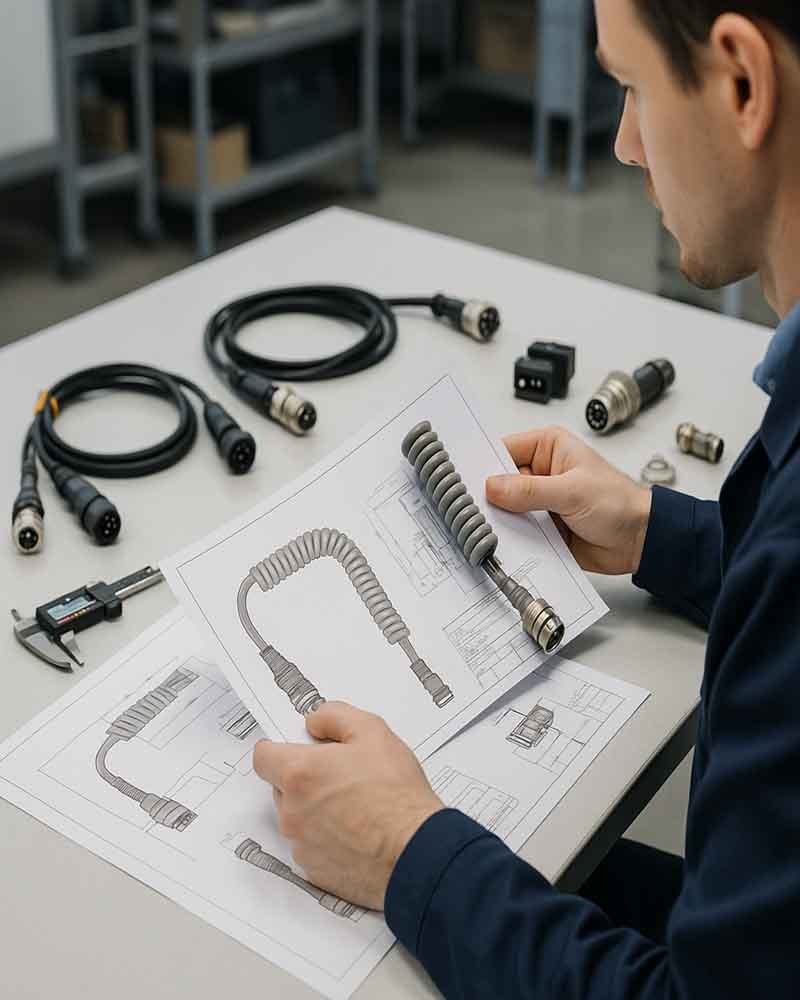
Start with mating interface, voltage/current or signal, mechanical space, environment, terminal and wire range, then supply conditions. Narrow to a connector family only after those inputs are defined. Exact series and P/N selection should also include keying, orientation, terminal system, cable exit and availability.
No. Equal pin count does not confirm pitch, keying, mating geometry, terminal position, electrical rating, sealing or signal performance. Compare the exact mating interface and terminal system. Any alternative should remain a candidate until mechanical, electrical, environmental and signal requirements are reviewed as applicable.
SINO-CONN supports cable assemblies using multiple connector ecosystems, including Molex, TE, JST, Hirose, I-PEX, JAE, Amphenol, Samtec and LEMO. Exact brand, series, P/N, sourcing route and availability are confirmed by project. Support for those systems does not imply authorized-distributor status.
Yes, when the program allows alternatives and the candidate passes the required review. Compare fit, keying, terminal and wire range, electrical rating, materials, sealing, signal behavior and documentation. Approved compatible parts should remain separate BOM items with clear source identity and project approval.
Send the mating connector, equipment photo, PCB or panel details, pin count, voltage/current or signal, available space, environment, cable length, quantity and target date. A sample, drawing, pinout or 3D space file can accelerate selection. Unknown fields can be left for engineering recommendation.
Timing depends on component availability and complexity. Stock items can move in same day to 2 working days; simple custom samples are typically 2-3 days; standard custom assemblies 3-7 days; complex builds 5-10 days. Tooling or long-lead connectors can extend the schedule.
Prototype evaluation can start from 1 piece when components are available. Regular OEM production is commonly planned from 100 pieces and regular ODM programs from 1,000 pieces, while pilot or special projects can be reviewed case by case. Connector SPQ or terminal reel quantity may still affect cost.
Not automatically. The mated connector, wire seals, rear cable entry, gland, backshell, cable OD, overmold and unmated condition all influence sealing. Define the required exposure and validate the finished configuration when a project-specific sealing target applies.
General harnesses commonly require continuity, open/short, pinout, visual and dimensional checks. Crimped contacts may require pull or cross-section checks. Power, RF, high-speed, waterproof or high-flex assemblies can add targeted electrical, signal, environmental or dynamic tests based on project risk.
Yes. Housing, terminal, seal, backshell and accessories can have different stock, SPQ, lead-time or lifecycle conditions. Availability should be checked against the exact P/N and required quantity at quotation time. Long-term programs should also consider EOL status, forecast and approved alternatives.

Send Your Connector Requirements For Engineering Review

Send the information already available, even if the connector has not been selected yet. SINO-CONN can review the interface from an exact P/N, drawing, sample, equipment photo, mating connector or functional requirement, then organize the missing items before quotation and prototype planning. A useful submission includes the fixed requirements first and leaves uncertain items open for engineering recommendation.
  • Connector: brand or P/N if known, mating side, pin count, pitch, keying and orientation.
  • Electrical or signal: voltage, current, protocol, frequency, impedance or special grounding needs.
  • Mechanical: cable length, branch, available space, exit direction, bend or movement condition.
  • Environment: temperature, water, oil, chemicals, vibration, cleaning or outdoor exposure.
  • Materials: wire AWG, cable type, shield, jacket preference, seal or overmold needs.
  • Commercial: prototype quantity, production quantity, annual estimate and target date.
  • Files: drawing, BOM, pinout, datasheet, photos, 3D space or existing sample.
If only a photo or mating connector is available, send it first. Engineering can identify missing information and define the next steps before a full RFQ package exists.

Ask For A Quick Quote

We will contact you within 24 Hours, please pay attentionto the email with the suffx”@sino-conn.com”.