Skip to content
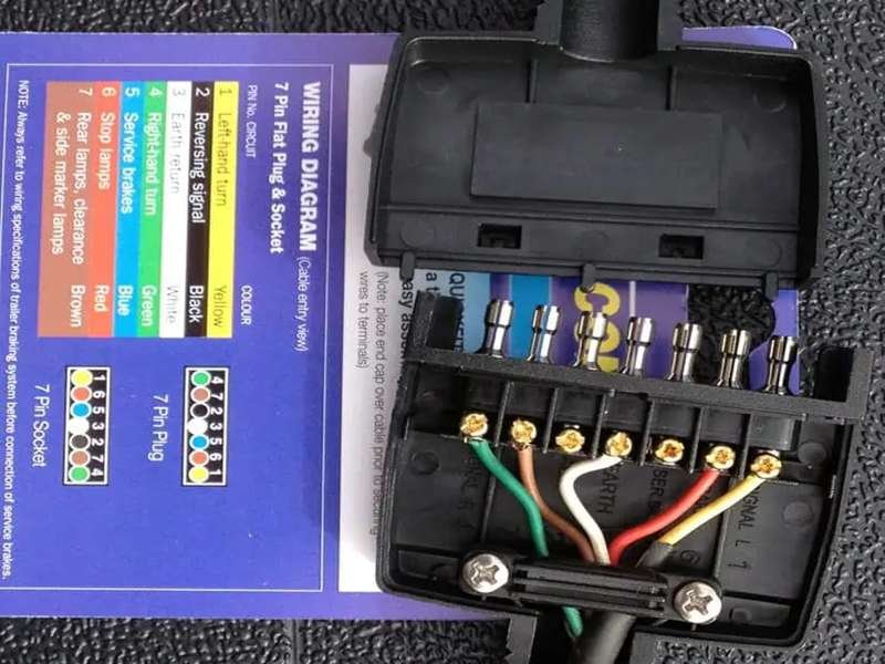
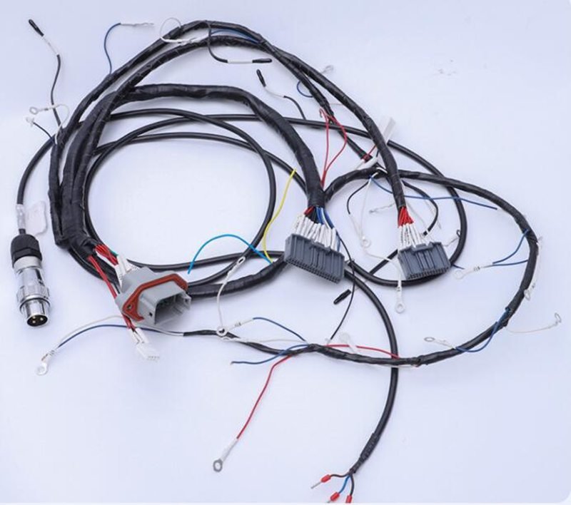
If you’ve ever hooked up a trailer and seen the rainbow of wires staring back at you, you probably wondered: Which one is ground, which is for brakes, and why does it look different than last time? Trailer wiring color codes are one of those details people assume are universal—but in reality, they’re not. Misinterpreting them can lead to frustrating electrical failures, safety hazards, or even roadside accidents.
Trailer wiring color codes identify the function of each wire in a trailer harness—ground, tail lights, left/right turn signals, brakes, or auxiliary power. Standard color codes exist for 4, 5, 6, and 7-pin plugs, but variations by region, vehicle type, or aftermarket kits make it essential to confirm before connecting. Correct color coding ensures safety, compliance, and reliable trailer operation.
Now imagine this: a logistics company outfits 50 trailers with “universal” harness kits, assuming all brown wires were tail lights. Weeks later, drivers report brake lights failing intermittently. It turns out the supplier used EU-style codes instead of U.S. DOT standards. Correcting the issue required rewiring, testing, and delaying shipments. That single oversight cost thousands. This is why knowing trailer wiring color codes isn’t trivia—it’s critical for safety, compliance, and business continuity.
What Are Trailer Wiring Color Codes?
Trailer wiring color codes assign colors to specific functions—ground, tail lights, brakes, turn signals, and auxiliary circuits. They matter because mismatched wiring leads to malfunctioning lights, brake failure, or non-compliant trailers. Following the correct color scheme ensures safe operation, reduces troubleshooting time, and keeps trailers in line with DOT and international standards.
At first glance, trailer wiring seems like a simple extension of automotive wiring. But trailers don’t have the same built-in controls or CAN bus systems as vehicles; instead, they rely on standardized plugs where each pin corresponds to a critical function. The only way to quickly and safely identify these functions is through consistent color coding.
Safety and Compliance
In North America, DOT regulations require specific lighting functions—running lights, brake lights, turn signals, and license plate lights—to work consistently. A trailer wired with incorrect colors may pass a visual inspection but fail under road conditions. This not only creates liability for the driver but also for the manufacturer or fleet operator.
Industry Efficiency
For mechanics and fleet managers, color codes are time savers. Imagine troubleshooting a 7-pin RV plug in the field: without a universal color scheme, technicians would spend hours with a multimeter verifying each circuit. Standardized color coding reduces that process to minutes.
Reducing Human Error in Installation
Most trailer owners are not electricians. They rely on guides, diagrams, and color codes to connect harnesses. If codes are inconsistent or undocumented, mistakes are inevitable. For example, connecting a blue wire (commonly electric brakes in U.S. standards) to auxiliary power instead could lock brakes at highway speeds—an obvious hazard.
Regional Variations
One complication is that U.S., EU, and Australian wiring standards differ. A trailer imported from Europe may use a different set of colors for brake or indicator lights than a U.S. pickup expects. This makes supplier documentation and verification critical, especially for OEMs serving multiple markets.
- U.S. 7-pin standard: Blue = brakes, Brown = tail lights.
- EU 7-pin (ISO 1724): Blue = fog lights, Brown = right turn.
- Australian 7-pin: Similar colors to U.S. but with different pin positions.
Which Standard Wiring Color Codes Are Commonly Used?
Standard trailer wiring color codes depend on connector type. 4-pin handles basic lights, 5-pin adds reverse or brake lockout, 6-pin supports brakes and auxiliary power, and 7-pin is the RV and heavy-duty standard. In U.S. DOT standards, white = ground, brown = tail lights, yellow = left turn/brake, green = right turn/brake, blue = brakes, black/red = auxiliary power, and purple = reverse. Always confirm with diagrams, since aftermarket and regional differences exist.
Trailer connectors come in several formats, and each format adds functionality through additional wires. Knowing which standard applies to your trailer is essential to ensure both safety and compliance.
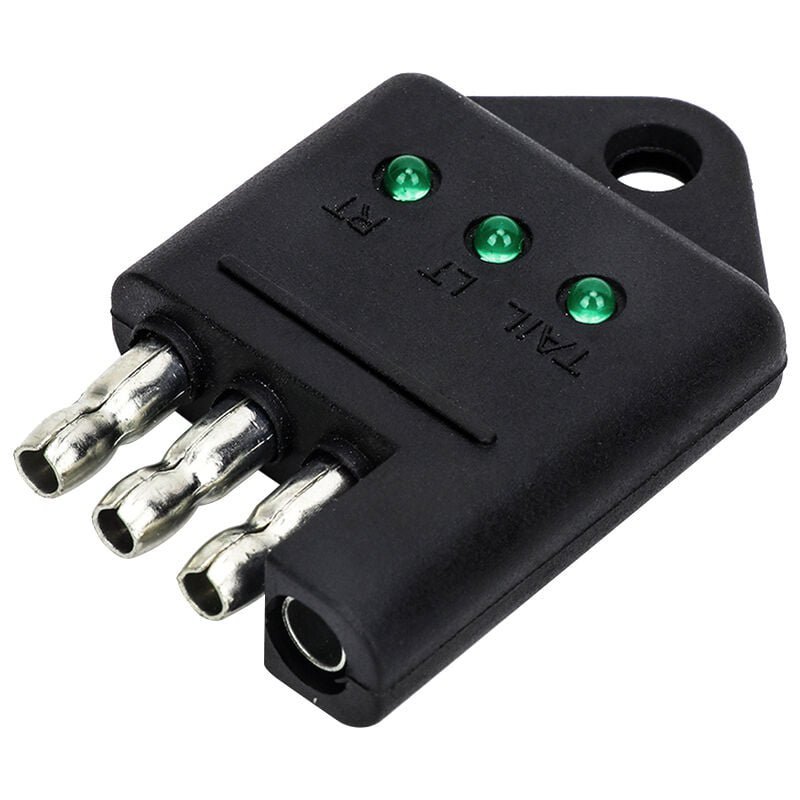
4-Pin Flat Trailer Wiring Color Codes (Utility & Light-Duty Trailers)
The most basic setup, typically used for small utility trailers, jet-ski trailers, and lightweight cargo carriers. Provides lighting only.
4-Pin Standard (U.S. DOT)
| Pin/Function | Wire Color | Description |
|---|---|---|
| Ground | White | Returns current to chassis |
| Tail/Running Lights | Brown | Powers rear, side marker, and license plate lights |
| Left Turn/Brake | Yellow | Left turn + brake light |
| Right Turn/Brake | Green | Right turn + brake light |
A common DIY mistake is confusing brown (tail lights) with yellow/green (brake/turn). This often leads to brake lights failing inspection while tail lights appear normal.
5-Pin Flat Trailer Wiring Color Codes (Boat Trailers)
Used mainly in boat trailers with surge brakes. The extra pin (blue wire) prevents brakes from locking when reversing down ramps.
5-Pin Standard (U.S. DOT)
| Pin/Function | Wire Color | Description |
|---|---|---|
| Ground | White | Return ground |
| Tail/Running Lights | Brown | Tail and marker lights |
| Left Turn/Brake | Yellow | Left indicator & brake |
| Right Turn/Brake | Green | Right indicator & brake |
| Reverse/Brake Lockout | Blue | Disables surge brakes when reversing |
Example: Without connecting the blue wire, a boat trailer may engage brakes while backing into water, straining the tow vehicle and damaging the brake system.
6-Pin Round Trailer Wiring Color Codes (Horse, Utility, Agriculture)
A step up in complexity, supporting electric brakes and 12V auxiliary power. Common in horse trailers, agricultural equipment, and medium-duty trailers.
6-Pin Standard (U.S. DOT)
| Pin/Function | Wire Color | Description |
|---|---|---|
| Ground | White | Chassis ground |
| Tail/Running Lights | Brown | Tail and marker lights |
| Left Turn/Brake | Yellow | Left turn & brake |
| Right Turn/Brake | Green | Right turn & brake |
| Electric Brakes | Blue | Controls trailer braking system |
| 12V Auxiliary Power | Red/Black | Battery charging or powering accessories |
7-Pin RV Blade Trailer Wiring Color Codes (Heavy-Duty & Standardized)
The industry standard for RVs, campers, and heavy-duty trailers, enabling full functionality: lights, brakes, auxiliary circuits, and reverse.
7-Pin RV Blade Standard (U.S. DOT)
| Pin/Function | Wire Color | Description |
|---|---|---|
| Ground | White | Ground return to chassis |
| Tail/Running Lights | Brown | Rear, side marker, license lights |
| Left Turn/Brake | Yellow | Left indicator & brake |
| Right Turn/Brake | Green | Right indicator & brake |
| Electric Brakes | Blue | Electric brake control line |
| 12V Battery/Power | Black/Red | Charges trailer battery, powers interior systems |
| Reverse Lights | Purple | Activates trailer backup lights |
Why It Matters: RVs rely on 7-pin connections for safety AND onboard systems (charging house batteries, powering fridges, running interior lights). Miswiring auxiliary power can disable entire systems or overheat wires.
Regional Differences in Color Standards
Trailer wiring is not globally uniform. Key differences include:
- Europe (ISO 1724, 11446): Blue = fog light, not brakes; brown = right turn.
- Australia: Similar color palette but different pin positions.
- Canada/U.S.: Follow SAE/DOT standards with blue = brakes.
Blue Wire Example Across Regions
| Region | Blue Wire Function |
|---|---|
| U.S. | Electric brakes / lockout |
| EU | Rear fog light |
| AUS | Service brakes |
Lesson: Always confirm with the plug diagram for your region.
How Do You Read and Apply Trailer Wiring Color Codes?
To read and apply trailer wiring color codes, match each wire’s color to its function—white for ground, brown for tail lights, yellow and green for left/right turn and brakes, blue for brakes, and black/red for auxiliary power. Always verify with a diagram or multimeter, since aftermarket kits and regional standards differ. Correct application ensures lights, brakes, and power systems work safely and prevents costly compliance issues.
Reading and applying trailer wiring color codes is about turning a wiring chart into a safe, working connection. A wire’s color is your first clue, but you must confirm it against standards and test it before finalizing. Here’s how to do it thoroughly.
Start with the Basics: Know the Standard Colors
In U.S. DOT wiring:
- White = Ground (always check first)
- Brown = Tail/Running Lights
- Yellow = Left Turn/Brake
- Green = Right Turn/Brake
- Blue = Brakes (electric or lockout)
- Black/Red = 12V Auxiliary Power
- Purple = Reverse Lights (7-pin)
Step-by-Step Application Process
Step 1: Identify Connector Type
Check whether your trailer has a 4-pin, 5-pin, 6-pin, or 7-pin connector. Each adds more functions (brakes, reverse, auxiliary).
Step 2: Reference the Correct Diagram
Use a wiring chart specific to your connector and region. Print it or keep it on your phone during installation.
Step 3: Strip & Prepare Wires
Strip 10–12 mm of insulation without nicking copper strands. Damaged strands reduce current capacity.
Step 4: Match Color to Function
Align each color-coded wire with its pin position. Example: On a 4-pin, white = ground, brown = tail, yellow = left, green = right.
Step 5: Confirm With a Multimeter
Check continuity and voltage:
- White → frame ground
- Yellow/Green → pulse with turn signal
- Blue → energized with brake controller
- Black/Red → constant 12V
Step 6: Secure & Seal Connections
Use heat-shrink crimp terminals or solder + adhesive shrink tubing for waterproofing.
Step 7: Final Testing
Connect trailer to vehicle and check all functions: running lights, left/right turn, brakes, reverse, and auxiliary circuits.
Regional & Manufacturer Differences
Trailer wiring codes are not universal.
- U.S. (SAE/DOT): Blue = brakes, Brown = tail lights.
- Europe (ISO 1724/11446): Blue = fog lights, Brown = right turn.
- Australia: Color palette similar to U.S., but pin layout differs.
Common Mistakes to Avoid
- Assuming OD = gauge: Outer jacket thickness doesn’t indicate conductor size.
- Ignoring ground integrity: A corroded or loose white wire is the #1 cause of light failure.
- Mixing up blue/black wires: Brake vs auxiliary power confusion causes serious failures.
- Skipping continuity testing: Never rely on colors alone—aftermarket kits sometimes substitute wire colors.
- Using automotive logic: Vehicle harness colors don’t always match trailer standards.
Practical Troubleshooting Example
Scenario: A fleet operator reports left brake lights not working.
- Expected: Yellow wire controls left turn/brake.
- Test: Multimeter shows no voltage on yellow when brakes applied.
- Root cause: Harness supplier swapped yellow with brown.
- Fix: Rewire using correct color-to-function mapping per DOT standard.
Industry-Specific Practices
- DIY Users: Rely on color codes + diagrams. Multimeter testing is critical.
- Fleet Mechanics: Use test boxes that simulate tow vehicle signals for fast checks.
- OEM Engineers: Require CAD drawings and spec sheets with explicit color mapping to avoid production errors.
U.S. 7-Pin Plug Functional Test Reference
| Function | Expected Color | Test Condition | Result |
|---|---|---|---|
| Ground | White | Continuity to frame | Pass |
| Tail/Running Lights | Brown | 12V with headlights on | Pass |
| Left Turn/Brake | Yellow | Pulses with left signal | Pass |
| Right Turn/Brake | Green | Pulses with right signal | Pass |
| Electric Brakes | Blue | Voltage on brake press | Pass |
| 12V Power | Black/Red | Constant 12V supply | Pass |
| Reverse Lights | Purple | 12V in reverse gear | Pass |
Do Color Codes Vary by Vehicle Type or Application?
Yes, trailer wiring color codes vary by vehicle type and application. Utility trailers usually use 4-pin codes, boat trailers often add a 5th pin for brake lockout, horse and agricultural trailers require 6-pin wiring for brakes and auxiliary power, and RVs or heavy-duty trailers standardize on 7-pin systems. OEM harnesses tend to follow stricter standards, while aftermarket kits may substitute colors. Always check the connector type and confirm with a diagram before wiring.
1. Utility Trailers
- Connector type: 4-pin flat
- Color codes: White (ground), Brown (tail), Yellow (left turn/brake), Green (right turn/brake)
- Functions covered: Only essential road lighting
- Use cases: Small cargo carriers, landscaping trailers, light-duty equipment
Key risk: If wired incorrectly, brake/turn signals won’t communicate with the tow vehicle, creating legal and safety violations.
2. Boat Trailers
- Connector type: 5-pin flat
- Extra wire: Blue (reverse/brake lockout)
- Why it matters: Without this wire, surge brakes may activate every time you reverse down a ramp.
- Environments: Saltwater or freshwater, requiring sealed connectors and corrosion-resistant insulation.
5-Pin Quick Reference
| Function | Color | Purpose |
|---|---|---|
| Ground | White | Chassis return |
| Tail/Running Lights | Brown | Rear/side markers |
| Left Turn/Brake | Yellow | Left side signaling |
| Right Turn/Brake | Green | Right side signaling |
| Reverse Lockout | Blue | Prevents brakes when reversing |
3. Horse & Agricultural Trailers
- Connector type: 6-pin round
- Extra functions:
- Blue = Electric brakes
- Red/Black = Auxiliary 12V for fans, lighting, or equipment
- Why it matters: Livestock and farm equipment need consistent braking and power delivery.
Industry Note: Agricultural trailers often run in harsh environments (mud, dust, chemicals). Wiring requires oil-resistant, UV-stable, and abrasion-resistant jackets.
Risk Example: If red auxiliary power is miswired as blue brakes, the trailer brakes may never engage—dangerous when hauling live animals.
4. RVs & Heavy-Duty Trailers
- Connector type: 7-pin RV blade
- Functions included: Lighting, brakes, auxiliary battery, reverse lights
- Color codes: White (ground), Brown (tail), Yellow (left turn/brake), Green (right turn/brake), Blue (brakes), Black/Red (battery power), Purple (reverse)
- Use cases: Travel trailers, fifth wheels, campers, long-haul trailers
Key concern: Miswiring auxiliary 12V power can disable onboard charging for RV systems (fridge, battery, lights).
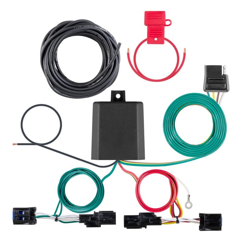
5. OEM vs Aftermarket Harnesses
OEM Harnesses:
- Follow documented standards
- Color codes are consistent
- QC tested before shipping
Aftermarket Harnesses:
- Often cheaper, but may use alternative wire colors
- Lack proper documentation
- Require multimeter testing before installation
OEM vs Aftermarket Comparison
| Factor | OEM Harness | Aftermarket Harness |
|---|---|---|
| Color Codes | Standardized, documented | May vary, sometimes inconsistent |
| QC Testing | 100% tested | Rare or inconsistent |
| Documentation | CAD + spec sheet | Often none |
| Risk Level | Low | High (miswiring, downtime) |
How to Troubleshoot Wiring Issues Using Color Codes?
To troubleshoot trailer wiring with color codes, start by checking the ground wire, then test each color-coded function (turn, brake, tail, auxiliary) with a multimeter. Look for mismatched colors, corroded connections, or swapped pins. Most issues stem from poor grounds or incorrect use of blue/black auxiliary wires. Confirming with color codes and continuity tests speeds up diagnosis and prevents repeated failures.
Even with correct color codes, trailer wiring failures happen. Corrosion, broken grounds, or swapped pins can cause partial or total system failure. Here’s a systematic approach.
Start with Ground (White Wire)
- Over 60% of trailer wiring problems are due to poor or corroded grounds.
- Check that the white ground wire is firmly connected to bare metal on the trailer frame.
- Use a multimeter to test continuity from plug ground to trailer frame.
Test Each Circuit by Color Code
Using a multimeter set to DC voltage:
- Brown (tail/running lights): Should show 12V when headlights are on.
- Yellow (left turn/brake): Pulses with left turn, solid with brake applied.
- Green (right turn/brake): Same as yellow but right side.
- Blue (brakes): Should show voltage when the brake controller is engaged.
- Black/Red (auxiliary): Should show constant 12V for battery charging.
- Purple (reverse): 12V only in reverse gear.
Troubleshooting Reference (U.S. 7-Pin RV Blade)
| Function | Expected Wire Color | Common Failure Point |
|---|---|---|
| Ground | White | Rusted or loose frame bolt |
| Tail/Running Lights | Brown | Broken splice or corrosion |
| Left Turn/Brake | Yellow | Cross-wired with right side |
| Right Turn/Brake | Green | Bulb failure or short |
| Electric Brakes | Blue | Miswired as auxiliary |
| 12V Battery Power | Black/Red | Fuse blown in tow vehicle |
| Reverse Lights | Purple | Not connected in older trailers |
Look for Regional Miswiring
If a trailer was imported, don’t assume U.S. colors apply. For example:
- EU trailers: Blue may power fog lights, not brakes.
- Australian trailers: Pin layout differs; colors sometimes match U.S. but functions don’t.
Solution: Always test function with the vehicle before trusting color alone.
Field Tools for Troubleshooting
- Multimeter: Essential for voltage/continuity checks.
- Circuit Tester (Light Probe): Faster for roadside troubleshooting.
- Trailer Tester Box: Simulates tow vehicle signals—ideal for fleet mechanics.
Preventing Repeat Failures
- Use heat-shrink connectors instead of bare crimps.
- Apply dielectric grease to prevent corrosion.
- Specify UV- and oil-resistant jackets for long-term durability (especially in fleets).
- Always label custom harnesses with both pin numbers and wire colors for clarity.
Sino-Conn Advantage in Troubleshooting
We help customers prevent wiring headaches by:
- Providing spec sheets and CAD drawings showing every wire color and pin mapping.
- Using ISO- and UL-certified materials that resist corrosion, UV, and chemicals.
- Supporting rapid replacement harnesses (samples in 2–3 days, urgent production in 2 weeks).
- Guaranteeing 100% QC testing—continuity, polarity, and load checks—before shipment.
For fleets, this means fewer roadside breakdowns. For OEMs, it ensures harnesses meet regional regulations without costly rework.
How to Specify and Order Custom Trailer Wiring Harnesses?
Specifying a trailer wiring harness isn’t as simple as saying “I need a 7-pin.” Engineers, OEMs, and fleet operators need to balance technical detail, compliance, and real-world durability. Missing one step can lead to harnesses that look correct but fail under load or during inspections. Here’s how to do it properly.
1. Define Conductor and Wire Specifications
- Gauge (AWG/mm²): Determines ampacity and voltage drop. For example, brakes may require 12 AWG, while marker lights may use 18 AWG.
- Strand count & material: Fine-strand copper improves flexibility, while tinned copper resists corrosion in marine trailers.
- Plating: Tin, nickel, or silver plating can add durability in harsh conditions.
Example: A 7-pin RV harness may require 12 AWG for brakes, 14 AWG for battery charging, and 18 AWG for lighting.
2. Specify Insulation and Jacket Properties
The insulation protects the conductor, while the outer jacket ensures mechanical and environmental resistance.
- Insulation: PVC (basic), XLPE (high-temp), PTFE (extreme heat/chemicals).
- Jacket: PVC for economy, TPU/TPE for flexibility, LSZH for fire safety, fluoropolymer for chemical resistance.
- Properties to note: Dielectric strength, temperature rating, abrasion resistance, UV stability.
Insulation Comparison Table
| Material | Temp Range | Key Strength | Weakness |
|---|---|---|---|
| PVC | -20–90°C | Affordable, flexible | Limited heat resistance |
| XLPE | -40–125°C | High-temp, oil resistant | Less flexible |
| PTFE | -65–200°C | Chemical, heat resistant | Expensive |
| LSZH | -30–105°C | Low smoke, halogen-free | Stiffer, higher cost |
3. Specify Connectors and Pin Mapping
- Connector Type: 4-pin flat, 5-pin flat, 6-pin round, 7-pin RV blade, or custom multi-pin.
- Pin Mapping: Explicitly state which wire color corresponds to which pin.
- Locking/Sealing Features: Waterproof connectors may be required for boat or agricultural trailers.
Sino-Conn delivers CAD-to-PDF drawings showing pin mapping, color coding, and connector geometry for client approval.
4. Include Shielding and EMI Requirements
Not all trailers need shielding, but applications with brake controllers, ABS sensors, or onboard electronics may.
- Foil Shield: Lightweight, cost-effective.
- Braided Shield: Strong EMI suppression.
- Combination Shield: Used in sensitive electronics or defense-grade harnesses.
5. Define Environmental and Mechanical Conditions
- Marine Trailers: Saltwater → tinned copper, sealed connectors, waterproof jacket.
- Agricultural Trailers: Exposure to mud/oil → oil- and abrasion-resistant jackets.
- RVs/Heavy-Duty: Long-haul → UV-resistant, flame-retardant insulation.
Failure Example: A farm trailer wired with standard PVC jacket suffered chemical degradation after six months. Specifying an oil-resistant XLPE jacket would have avoided downtime.
6. Compliance and Certification
Regulatory compliance is non-negotiable. Always specify certifications:
- UL & ISO9001/14001: Quality assurance.
- RoHS, REACH, PFAS-free: Environmental standards.
- DOT/SAE or MIL-SPEC: For regulated markets.
Skipping compliance can result in failed inspections, customs delays, or recalls.
7. Request CAD Drawings and Samples
- Drawings: Verify wire gauge, colors, pin mapping, and connector orientation. Sino-Conn provides them in 30 minutes–3 days.
- Samples: Always test in the field before mass order. Sino-Conn ships urgent samples in 2–3 days.
8. Clarify MOQ and Lead Times
- MOQs: Many suppliers require 500+ units; Sino-Conn supports no MOQ, starting from 1 prototype.
- Lead Times:
- Samples: 2–3 days (urgent), 2 weeks (standard)
- Mass production: 3–4 weeks
Flexibility benefits R&D engineers who need fast prototyping.
9. Quality Control and Testing
A supplier’s QC process determines harness reliability. Sino-Conn performs:
- 100% continuity and polarity tests
- Ampacity and load simulation
- Insulation breakdown voltage tests
- Mechanical pull/bend tests
QC Checklist Example
| Test | Method | Purpose |
|---|---|---|
| Continuity Check | Multimeter/Tester | Ensures all circuits connected |
| Load Test | Simulated current | Confirms ampacity |
| Hi-Pot Test | Voltage stress | Verifies insulation integrity |
| Pull/Bend Test | Mechanical strain | Ensures durability in use |
Frequently Asked Questions
1: What is the standard trailer ground wire color?
In U.S. DOT standards, the ground wire is white. It should be firmly connected to the trailer frame to ensure all circuits function correctly.
2: Which color is used for trailer brake lights?
The yellow wire controls the left turn/brake light, and the green wire controls the right turn/brake light in most U.S. trailers.
3: What does the blue wire do in trailer wiring?
In U.S. 5-, 6-, and 7-pin systems, the blue wire usually powers electric brakes. In boat trailers, it may also control surge brake lockout.
4: Do trailer wiring color codes differ between countries?
Yes. The U.S., EU, and Australia follow different wiring standards. For example, blue wires may mean brakes in the U.S. but fog lights in Europe.
5: What size connector do small utility trailers use?
Most small utility and light-duty trailers use a 4-pin flat connector, covering ground, tail, and left/right turn/brake lights.
6: How can I test trailer wiring color codes?
Use a multimeter or test light. Check each wire: brown for tail lights, yellow for left turn, green for right turn, blue for brakes, and confirm voltage output matches function.
7: What is the difference between a 6-pin and 7-pin trailer connector?
Both support electric brakes and auxiliary power, but a 7-pin adds reverse lights (purple wire) and is the standard for RVs and heavy-duty trailers.
8: Why do trailer lights work intermittently?
The most common cause is a bad ground (white wire). Corrosion, loose bolts, or poor frame connections can disrupt lighting circuits.
9: Can I connect wires by color alone without checking a diagram?
No. While color codes are guidelines, some aftermarket harnesses reuse different colors. Always confirm with a wiring diagram or CAD drawing.
10: How do I order a custom trailer wiring harness from Sino-Conn?
Provide specifications such as connector type, wire gauge, color coding, shielding, insulation, and certification requirements. Sino-Conn offers CAD drawings, no-MOQ samples, and 100% QC testing to guarantee accuracy and compliance.
Conclusion
Trailer wiring color codes may look like a mess of colored wires—but they carry the entire safety and reliability of your trailer. From 4-pin utility plugs to 7-pin RV connectors, each color carries a function that can make the difference between smooth operation and roadside failure. Misinterpreting them risks accidents, compliance issues, and costly rework.
Whether you’re an OEM engineer, fleet manager, or trade buyer, Sino-Conn helps you get it right the first time—no rewiring, no failed inspections, no downtime.
Contact Sino-Conn today to request a free consultation or custom trailer wiring harness quote.