Skip to content
 Connecting two USB cables might sound like a simple, everyday fix. Maybe your device is just a little too far from your desk, or you need extra length for your setup at home or in the lab. But here’s the catch: USB isn’t just about plugging in—it’s about power, data speed, and safety. If you join cables incorrectly, you risk slow transfers, unstable charging, or even device damage.
The safest way to connect two USB cables is by using a certified USB extension cable, a female-to-female coupler, or a powered hub. These methods maintain signal integrity, support proper voltage, and ensure safe power delivery. Avoid DIY splicing or unsupported adapters, as they can cause data loss, overheating, or equipment damage.
The problem is, many users try the “quick and dirty” way—like splicing wires or using cheap adapters they find online. That often works for a short while, until a hard drive disconnects mid-transfer or a phone overheats during charging. In professional environments, these failures can cost money, time, and even customer trust.
Imagine an engineer running a firmware update on a medical device, only for the USB link to fail because of a poor cable connection. Or a gamer who adds an extension cable, only to see latency spikes ruin performance. These are real-world risks—and they show why connecting USB cables isn’t trivial. Let’s break down the right way to do it.
What Does It Mean to Connect Two USB Cables?
Connecting two USB cables means joining them to extend length, adapt between connectors, or bridge two devices. While simple in theory, not all methods are safe: USB carries both power and data, and mismatched connections can cause performance issues or hardware damage. The correct approach depends on your goal—charging, data transfer, or specialty functions like DisplayPort Alt Mode.
At first glance, “connecting two USB cables” might sound straightforward: you’ve got two cords, and you want them to act as one. But in reality, USB is a spec-driven ecosystem with precise rules on how hosts, devices, hubs, and cables interact.
Different Types of USB Cables
- USB-A to USB-B: Common for printers, scanners, and legacy devices.
- USB-A to Micro/Mini: Used in older phones, cameras, and accessories.
- USB-C to USB-C: Increasingly standard for smartphones, laptops, and tablets.
- USB-C to HDMI/DisplayPort: Alternate Mode cables for video output.
Each type carries different roles in the system. For example, USB-A is almost always a “host” end, while USB-C can be dual-role (power or data). Connecting them incorrectly—say, host-to-host—violates the standard and risks backfeeding power into devices.
Why People Connect USB Cables
There are several common scenarios:
- Extending reach: The most frequent case. A USB cable isn’t long enough to reach a PC, charger, or industrial machine, so users want “more length.”
- Adapting connectors: For example, connecting a USB-A device to a USB-C port via couplers or adapters.
- Bridging two hosts: A dangerous but common misconception is trying to connect two computers with a plain USB-A to USB-A cable.
- Industrial or OEM applications: Engineers may need custom lengths, pinouts, or shielding levels that standard cables don’t offer.
So in practice, “connecting two cables” usually means either extending length or changing the connector type.
Risks of “Just Plugging Together”
USB carries both voltage and current—typically 5V up to 3A, but with USB-PD it can reach 20V and 5A (100W) or even 48V/5A (240W). That’s no longer “just charging your phone”—it’s industrial-level power.
Improper connections can lead to:
- Overheating: Thin wires or poor joints can’t handle high current.
- Signal degradation: Data lines (D+/D- for USB 2.0, differential pairs for USB 3.x) are sensitive to impedance mismatch.
- Device failure: Host-to-host risks creating voltage loops.
Host vs Device Roles
USB isn’t peer-to-peer by default. One side is usually the host (PC, charger, hub), and the other is the device (phone, printer, external drive). Connecting two “hosts” together (like two PCs) without a proper USB bridge cable can cause:
- Power backfeeding (both ports try to supply 5V, creating conflict).
- Potential port or motherboard damage.
This is why a standard “USB-A male to USB-A male” cable is not recommended.
Safe vs Unsafe Methods
Safe:
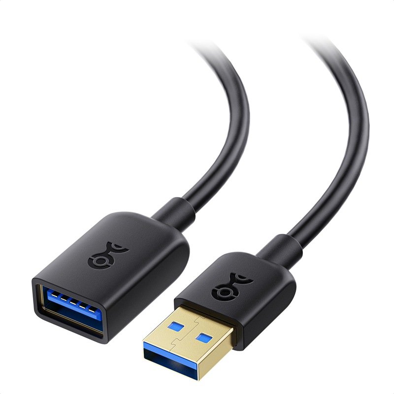
- Using a certified extension cable (male to female).
- Using a female-to-female coupler with compatible cables.
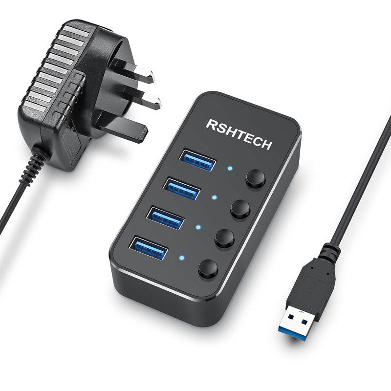
- Using an active hub or repeater to extend length beyond spec.
Unsafe:
- DIY soldering/splicing without shielding.
- Host-to-host plain connections.
- Cheap adapters with no compliance testing.
Hidden Technical Parameters
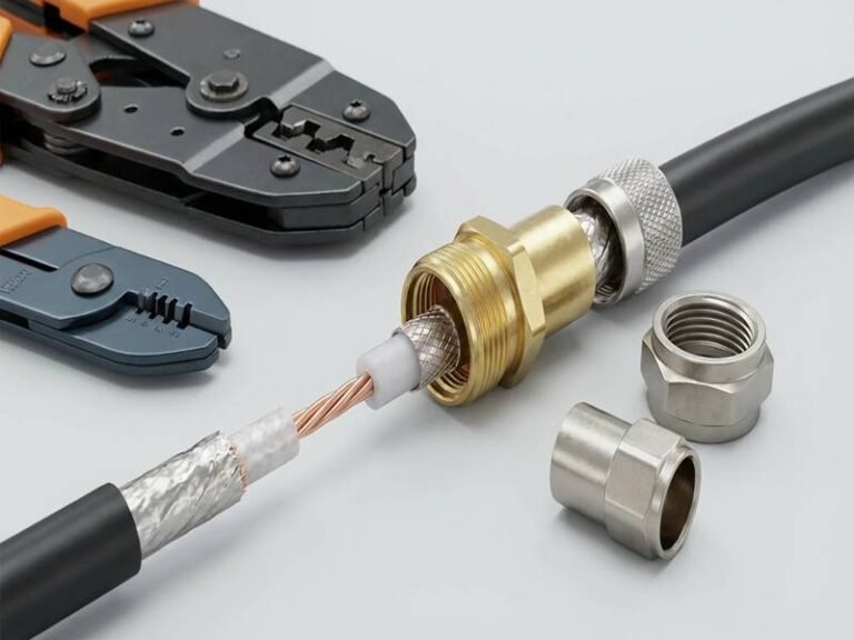
When customers send Sino-Conn just a photo of a cable, they often underestimate how many hidden parameters matter:
- Outer Diameter (OD): Determines bend radius and durability.
- Impedance: Critical for high-speed signal integrity.
- Shielding: Foil and braid for EMI resistance.
- Conductor gauge (AWG): Affects voltage drop and current capacity.
- Material: Halogen-free, flame-retardant, oil/UV resistant for industrial use.
For example, two cables may look identical in a picture, but one can safely carry 100W PD while the other fails at 15W.
Safe vs Unsafe USB Connections
| Scenario | Safe? | Notes |
|---|---|---|
| Male-to-female extension cable | Yes | Keep within spec length |
| Female-to-female coupler | Partial | OK for USB 2.0, risky for high-speed |
| Powered hub/repeater | Yes | Refreshes signal + power |
| USB bridge cable (PC-to-PC transfer) | Yes | Includes embedded controller |
| DIY splicing/soldering | No | Risky for data + power |
| Plain A-to-A male cable | No | Can damage devices |
Which Methods Work to Join Two USB Cables?
You can join USB cables safely using certified extension cables, female-to-female couplers, active extension cables, powered hubs/repeaters, or USB bridge cables for PC-to-PC transfer. Each method has different limits for data speed, cable length, and power delivery. Unsafe shortcuts—like DIY splicing or plain male-to-male connections—risk overheating, voltage drops, or device damage. For industries where compliance and reliability are critical, the best option is custom cable assemblies designed with proper shielding, pinouts, and certifications.
On the surface, connecting two USB cables feels like a simple length problem—“I just need more reach.” But USB is governed by strict specifications for data transmission and power safety. That’s why some methods are perfectly safe, while others can cause device malfunctions or even permanent damage. Let’s look at all the major methods, their pros and cons, and when to use each.
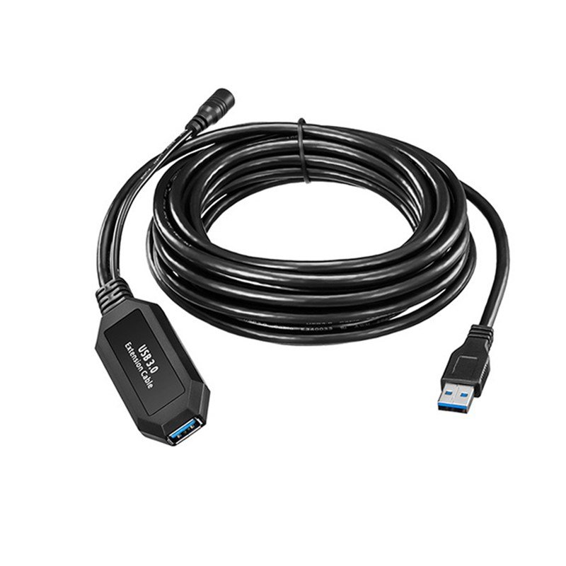
USB Extension Cables (Most Common Solution)
A male-to-female cable designed to add length to an existing USB run.
Why it works: It’s compliant with USB specs for impedance and shielding, so as long as you respect length limits, your signal remains intact.
Technical Limits:
- USB 2.0 → up to 5 meters passive.
- USB 3.0/3.1 → 2–3 meters passive before dropouts.
- USB4 (40Gbps) → ~0.8 meters passive, unless using active cables.
Use Case Example: A designer connects a drawing tablet 3 meters away from their workstation. A USB 3.0 extension cable maintains stable performance, avoiding lag that would occur with cheap couplers.
Female-to-Female Couplers (Simple but Risky)
A small plastic adapter with two female ports, letting you join two standard male cables.
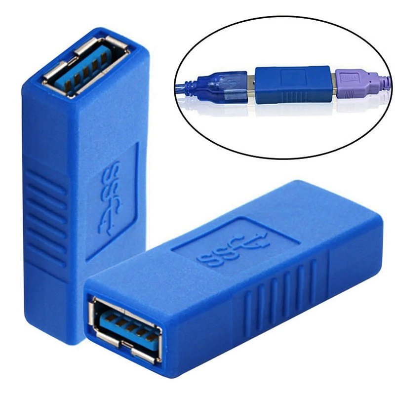
Why people use it: Inexpensive, plug-and-play, no need to buy a new long cable.
Weaknesses:
- Works fine for USB 2.0 low-speed devices like keyboards, mice, or printers.
- At USB 3.0 or higher, couplers often break shielding continuity, leading to data errors, reduced speed, or interference.
- Not recommended for high-bandwidth tasks like transferring large files to SSDs.
Example: A gamer used a coupler to extend a USB-C SSD connection. The drive dropped from 1,000 MB/s to 40 MB/s due to poor signal quality.
Powered USB Hubs (Best for Multiple Devices)
An active device that connects multiple peripherals while regenerating the USB signal and supplying independent power.
Benefits:
- Overcomes passive cable length limits by refreshing the signal.
- Prevents overloading the host port, since the hub supplies its own power.
- Allows multiple devices to share one port.
Limitations:
- Requires external power.
- Adds hardware cost.
Use Case Example: In a photography studio, a DSLR camera tethered via USB would disconnect at 8m. Adding a powered USB hub stabilized the connection, enabling continuous image capture during shoots.
Active USB Extension Cables (With Signal Boosters)
Similar to an extension cable, but with built-in active electronics that amplify data signals.
Why it’s useful:
- Maintains high-speed USB 3.x/4.0 performance over longer runs.
- Supports professional setups like VR gaming, medical imaging, and video production.
Downside: More expensive than passive extensions.
Example: A VR headset required a stable 5m USB 3.1 connection. Passive cables failed, but an active repeater cable maintained latency-free performance.
USB Bridge Cables (Safe PC-to-PC Transfers)
A cable with embedded electronics that allows two host devices (like PCs) to connect safely.
Why it matters:
- Prevents back-power conflict that happens with plain A-to-A cables.
- Used for file transfers, PC migration, or diagnostics.
Warning: Never use a plain male-to-male USB-A cable between computers—it risks burning out ports.
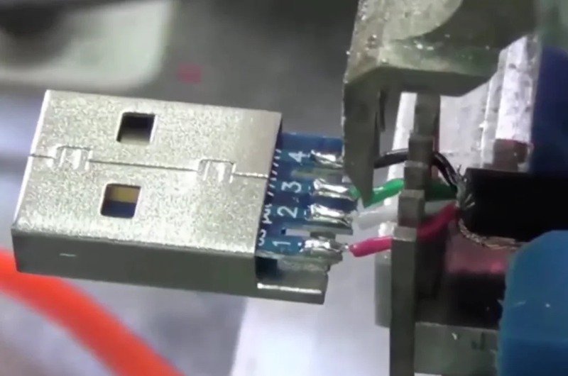
DIY Splicing or Soldering (Unsafe for Most Cases)
Cutting two cables and manually soldering wires together.
Risks:
- Signal issues: Twists and shielding are broken, causing EMI.
- Power safety: Weak joints can overheat at 100–240W PD loads.
- Durability: Fails under bending and mechanical stress.
When acceptable: Only for low-power charging of toys or small gadgets, not for high-speed or industrial use.
Real Example: An automotive OEM tried splicing USB harnesses in prototype vehicles. Result: frequent disconnects in infotainment systems. Switching to Sino-Conn’s shielded harnesses solved the problem and passed global compliance tests.
OEM Custom Cable Assemblies (Best Long-Term Solution)
For businesses, none of the consumer-level fixes provide guaranteed reliability. That’s where custom USB assemblies come in.
Advantages of Custom Assemblies:
- Exact lengths: From short (<0.3m) to extended industrial runs.
- Pinouts & Definitions: Custom wiring (important for R&D).
- Materials: Flame-retardant, halogen-free, UV/oil-resistant jackets.
- Shielding: Multiple layers for EMI protection.
- Certifications: UL, ISO, RoHS, REACH, PFAS.
- MOQ: Sino-Conn can start at 1 piece for prototyping, unlike mass-market vendors.
Process at Sino-Conn:
- CAD drawings delivered in 30 minutes–3 days for confirmation.
- Samples in 2–3 days for urgent cases.
- Mass production in 2–4 weeks, depending on order size.
- 100% inspection: in-process, finished, and pre-shipment.
Result: You get cables designed to your specs, tested for compliance, and optimized for your market (medical, aerospace, automotive, consumer electronics).
USB Joining Methods
| Method | Safe? | Speed Support | Best For | Risks/Limitations |
|---|---|---|---|---|
| USB Extension Cable | Yes | USB 2.0–3.2 | Simple extensions | Spec length limit |
| Female-to-Female Coupler | Limited | USB 2.0 only | Quick low-speed fixes | Drops speed at high data rates |
| Powered USB Hub | Yes | All versions | Long runs, multi-devices | Extra power supply needed |
| Active Extension Cable | Yes | USB 3.x / USB4 | VR, pro AV setups | Higher cost |
| USB Bridge Cable | Yes | PC-to-PC only | Safe host-to-host transfers | Niche use only |
| DIY Splicing | Unsafe | Unreliable | Emergency charging only | Heat, EMI, failure risk |
| Custom Cable Assembly | Optimal | All versions + PD | Industrial & OEM applications | Production lead time |
How Do Signal Integrity and Power Affect Connection?
Signal integrity and power delivery define whether two joined USB cables will function reliably. Poor shielding, impedance mismatches, or thin wires cause data errors, slow speeds, and charging failures. With USB4 carrying 40Gbps and USB-PD delivering up to 240W, even small flaws—like voltage drop or EMI interference—can make connections unstable. Certified or custom assemblies with proper AWG conductors, 90Ω impedance control, and multi-layer shielding are essential for industrial or high-performance use.
Signal Integrity: Keeping Data Clean
USB is a digital standard, but the signals riding inside the cables are analog voltage waveforms. They are vulnerable to loss, distortion, and interference.
Key technical aspects:
- Differential Impedance (~90Ω): Data lines (D+ and D− in USB 2.0; multiple high-speed lanes in USB 3.x/4) are tightly twisted to achieve ~90Ω impedance. A coupler that shifts impedance even by ±10Ω creates reflections, distorting the waveform.
- Attenuation (Insertion Loss): Every meter of cable introduces resistance and capacitance. Beyond ~3m, USB 3.0 (5Gbps) signals attenuate enough that receivers may downshift to USB 2.0 speeds (480Mbps).
- Crosstalk: High-speed USB lanes sit next to each other. Without solid shielding, one lane’s signal leaks into another, causing jitter and packet errors.
- Electromagnetic Interference (EMI): In factories or offices full of motors, Wi-Fi, and power supplies, unshielded joints act like antennas. EMI causes disconnects at random, which end-users perceive as “USB not recognized.”
Typical USB Signal Loss by Cable Length
| USB Standard | Max Passive Cable Length | Performance Impact if Exceeded |
|---|---|---|
| USB 2.0 (480 Mbps) | ~5 meters | Signal degradation, retry packets |
| USB 3.0 (5 Gbps) | 2–3 meters | Downshifts to USB 2.0 speeds |
| USB 3.2 (10–20Gbps) | 1–2 meters | High BER (bit error rate) |
| USB4 (40 Gbps) | 0.8 meters (passive) | Complete failure without active link |
Power Delivery: More Than Just “Charging”
Originally, USB delivered only 5V at 500mA. Today, USB Power Delivery (PD 3.1) supports up to 48V at 5A (240W). That’s enough to power gaming laptops, docking stations, or even industrial sensors.
But with higher power comes higher risk.
- Voltage Drop: The longer the cable, the more resistance. Example: A 28AWG wire (~0.22Ω/m). Over 5m at 5A, that’s a 5.5V drop—meaning your laptop might only see ~42.5V instead of 48V.
- Overheating: Underrated joints or thin wires act as resistors. At 100W loads, they become hot spots, leading to melting insulation or connector damage.
- PD Negotiation Failures: USB-PD isn’t just wires—it’s a protocol. If a coupler or poor cable interferes with CC (configuration channel) signals, devices may fall back to 5V/500mA or refuse to charge.
Conductor Gauge vs Current Carrying Capacity
| Wire Gauge (AWG) | Max Current (USB PD) | Use Case |
|---|---|---|
| 30 AWG | 0.5A | Data lines only |
| 28 AWG | 1–1.5A | USB 2.0 low-power charging |
| 24 AWG | 2–3A | USB 3.0 standard charging |
| 20 AWG | 5A | USB-PD 100–240W |
The Double Challenge: High Speed + High Power
With USB4, we now combine 40Gbps differential signaling with 240W PD—in the same cable. That means:
- Data lanes need perfect impedance matching and shielding.
- Power lines need low-resistance copper (20AWG or thicker).
- The overall cable OD (outer diameter) must balance flexibility and durability.
Joining two consumer-grade cables with a coupler introduces weak links—breaking shielding continuity, adding resistance, and risking EMI ingress.
Industry-Specific Consequences
- Medical Equipment: A USB disconnect during an MRI scan could corrupt imaging data. Hospitals demand double-shielded, medically rated cables.
- Automotive: Vehicle infotainment USB failures during prototype testing can delay product launches by months. Car OEMs use custom harnesses with braided shielding and fire-retardant jackets.
- Aerospace/Defense: High EMI + safety regulations mean only cables tested for fire, oil, UV resistance, and EMI suppression are accepted.
How Professionals Verify Integrity
Top-tier suppliers like Sino-Conn don’t just promise—they test:
- Time-Domain Reflectometry (TDR): Checks impedance uniformity.
- Eye Diagram Testing: Visualizes jitter and noise at high speeds.
- Voltage Drop Tests: Ensures cables deliver rated PD wattage.
- EMI/EMC Testing: Confirms shielding effectiveness.
- Mechanical Testing: Flex cycles (10k+), tensile strength, bend radius.
In contrast, DIY splices or cheap couplers skip all of these, leaving users to discover failures in the field.
Risks vs Controls
| Risk | Cause | Impact | Control |
|---|---|---|---|
| Data Reflections | Impedance mismatch | Bit errors, downshift to USB 2.0 | 90Ω design & TDR testing |
| EMI/Crosstalk | Broken shielding | Random disconnects | Foil + braid shielding |
| Voltage Drop | Thin wires, long length | Slow or failed charging | 20–24 AWG conductors |
| Overheating | Bad splices, weak joints | Burned ports, melted jackets | OEM solder + QC tests |
| PD Protocol Failure | Poor couplers blocking CC lines | PD not negotiated, defaults to 5V | Certified or custom assemblies |
Do DIY Splicing and Soldering Work for USB Cables?
DIY splicing and soldering can physically join two USB cables, but they often lead to poor performance, unsafe power delivery, and unreliable data transfer. Without precise shielding, impedance control, and proper materials, spliced cables may overheat, lose speed, or damage connected devices. For professional or industrial use, experts recommend certified extensions or custom-manufactured USB assemblies instead of DIY fixes.
For hobbyists, the idea of cutting and soldering two USB cables together feels intuitive: strip the wires, match the colors, twist or solder them, add some tape or heat shrink, and voilà—you’ve got a “longer” USB cable. In reality, though, USB is not that forgiving.
Signal Degradation from DIY Splicing
- Impedance mismatch: USB requires ~90Ω balanced impedance on data lines. Even slight variation from sloppy solder joints creates reflections, which corrupt signals.
- Crosstalk: Data pairs are twisted for a reason—if spliced poorly, untwisted wires pick up noise, dropping performance from 10Gbps to USB 2.0 speeds.
- No shielding continuity: Cutting the foil or braid means losing EMI protection, especially critical in industrial or medical environments.
Power Safety Issues
- Thin joints heat up: If carrying USB-PD at 60W, a poor solder joint becomes a hot spot.
- Voltage drop: Even 0.5V lost across a bad splice can cause a device to fail.
- Short circuits: Poor insulation may let wires touch, risking port damage or fire.
Testing & Reliability Concerns
Professional assemblies undergo high-pot testing, continuity checks, and insertion loss measurement. DIY splices usually skip this, leaving users to discover failures the hard way—during a firmware update, file transfer, or charging session.
Industrial Case Example
One OEM client in automotive tried DIY splicing to extend USB runs in prototype vehicles. The result? Frequent disconnects in infotainment systems. After switching to Sino-Conn’s custom-built harnesses with EMI shielding and automotive-grade sheathing, error rates dropped to 0.01%, and they passed compliance testing for global markets.
Verdict on DIY Splicing
DIY works for low-power charging of gadgets when performance isn’t critical. But for any professional or industrial application, it’s a liability. The hidden costs—rework, downtime, or device damage—far outweigh the small savings of skipping a proper solution.
Comparison: DIY Splicing vs Custom Cable Assemblies
| Feature | DIY Splicing | Custom Assembly (Sino-Conn) |
|---|---|---|
| Signal Integrity | Poor, unstable | Verified, 90Ω impedance |
| Power Safety | Risk of overheating | Rated for 60–240W USB-PD |
| EMI Shielding | Often lost | Foil + braided shielding |
| Durability | Short-term | Tested for 10k+ flex cycles |
| Certification | None | UL, ISO, RoHS, REACH |
| Cost in Long Term | High (failures, repairs) | Lower (stable supply chain) |
Are There Safer Alternatives to Cable-to-Cable Joining?
Yes. Safer alternatives include USB extension cables, powered hubs, active repeater cables, USB-over-Ethernet/fiber extenders, USB bridge cables, and most importantly, OEM custom assemblies. Each method is engineered to maintain signal integrity, power stability, and compliance. Unlike DIY splicing or random couplers, these alternatives are tested against standards, ensuring reliability for both consumers and industries. The best option depends on the application: casual users can rely on extensions, while medical, automotive, and aerospace buyers should choose custom-certified assemblies.
USB Extension Cables: The Everyday Fix
A male-to-female cable that increases the distance between a device and its host.
Why it’s safe:
- Designed with controlled impedance (~90Ω).
- Maintains twisted pair geometry for data integrity.
- Keeps EMI shielding intact end-to-end.
Limits by USB version:
- USB 2.0 (480 Mbps): ~5 meters max.
- USB 3.0/3.1 (5–10Gbps): ~2–3 meters max.
- USB4 (40Gbps): ~0.8 meters passive.
Example: A home office user with a webcam too far from their laptop used a 2m USB 3.0 extension. Result: smooth HD video. When they tried a coupler + second cable, the webcam froze randomly due to EMI.
Tip: Extension cables are excellent for casual setups—but never stretch beyond spec if data stability matters.
2. Powered USB Hubs: Active and Scalable
Active hubs that re-drive USB signals and provide their own regulated power.
Advantages:
- Signal Regeneration: Prevents attenuation from long passive runs.
- Independent Power Supply: Devices draw from the hub, not the host, preventing overload.
- Expandability: One host port supports multiple devices.
Case Study: A U.S. video-editing studio ran external drives, MIDI controllers, and cameras via a powered hub. Without it, voltage drop caused drive disconnections mid-session. With the hub, all devices remained stable.
Limitations:
- Requires AC power.
- Adds hardware cost.
Use Case: Ideal for studios, labs, and offices with many peripherals.
3. Active Extension Cables: Smarter Long Runs
Extension cables with built-in electronics (repeaters or equalizers) that amplify and clean signals.
Why they’re critical:
- Maintain USB 3.x/USB4 performance over 5–15m runs.
- Prevent packet retransmissions, saving speed and CPU resources.
Applications:
- VR gaming (Oculus/Meta headsets).
- Medical imaging.
- Industrial control panels requiring long connections.
Case Study: A Chinese OEM using robotic arms with cameras faced random disconnects on 7m USB 3.1 passive runs. Switching to active repeater cables eliminated dropouts, improving production efficiency by 15%.
Tip: If your cable run exceeds spec limits, only active cables can guarantee full performance.
4. USB Repeater Chains (Hub + Active Extension)
A series of powered hubs or active repeaters, chained to reach 20–30m.
Why it works: Each hub “refreshes” signals, avoiding cumulative degradation.
Use Case:
- Conference halls with ceiling-mounted USB cameras.
- Industrial floors with widely spaced machinery.
Limitations:
- More complex installation.
- Requires multiple power sources.
5. USB-over-Ethernet/Fiber Extenders: Industrial Grade
Devices that convert USB signals into Ethernet or fiber signals for long-distance transmission (50–100m+).
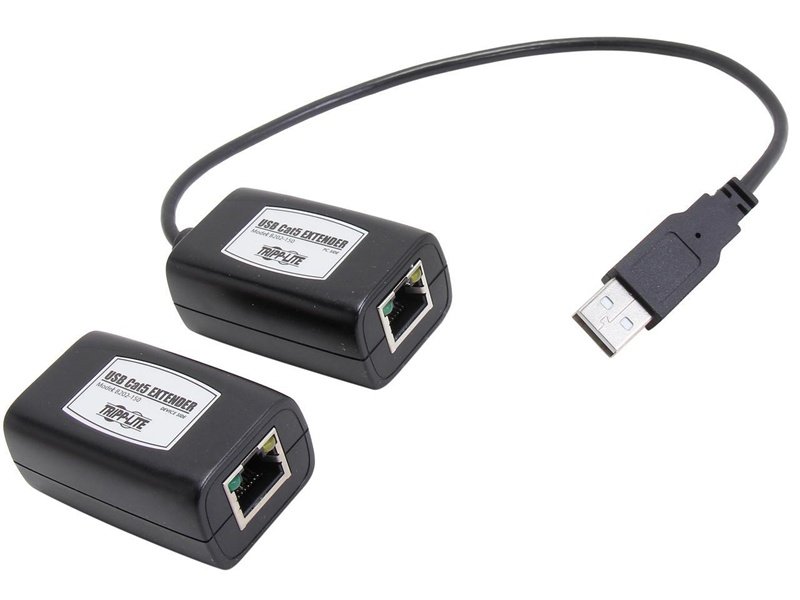
Advantages:
- Ethernet: Leverages Cat6/Cat7 cabling. Cost-effective, easy to install.
- Fiber: Absolute EMI immunity. Perfect for hospitals, defense, and aerospace.
Applications:
- Medical labs (EMI-heavy environments).
- Aerospace R&D (clean rooms).
- Secure facilities (fiber is tamper-resistant).
Case Study: An aerospace contractor used USB-over-fiber to link test instruments across shielded labs. Passive USB failed at 3m; fiber delivered stable, interference-free 100m runs.
Limitations:
- Expensive compared to extensions.
- Overkill for consumer setups.
Tip: Choose fiber if EMI is your biggest threat; choose Ethernet extenders if distance is the challenge.
6. USB Bridge Cables: Safe PC-to-PC Transfers
What they are: Cables with embedded controllers to allow safe host-to-host connections.
Why it matters:
- Prevents back-powering, which can fry ports.
- Includes software for safe data migration.
Example: IT teams migrating hundreds of laptops use USB bridge cables to transfer user profiles without relying on networks.
Limitation:
- Niche use—only for PC-to-PC transfer.
Warning: Plain A-to-A male cables are dangerous. Always choose certified bridge cables.
7. OEM Custom Cable Assemblies: The Professional Answer
For industries, custom assemblies are the gold standard.
Key Features:
- Length: Defined to exact mm tolerance.
- Pinouts/Definitions: Custom mapping (critical in R&D).
- Materials: Fire-retardant, halogen-free, oil-resistant, UV-resistant.
- Shielding: Foil + braid for EMI-critical environments.
- Certifications: UL, ISO9001/14001, RoHS, REACH, PFAS-free.
Sino-Conn Advantages:
- CAD drawings in 30 min–3 days.
- Samples in 2–3 days (rush).
- Mass production in 2–4 weeks.
- No MOQ: Start from 1 piece.
- 100% QC: In-process, post-production, pre-shipment.
Case Study: A European medical OEM needed 240W USB-PD 3.1 cables for surgical carts. Off-the-shelf options failed EMI testing. Sino-Conn engineered a 20AWG power + double shielding solution, approved in 2 weeks, passing EU medical standards.
Alternatives Comparison Table
| Method | Max Length | Speed Support | Best For | Risks/Limitations |
|---|---|---|---|---|
| USB Extension Cable | 2–5m | Up to USB 3.2 | Home/office | Limited by spec |
| Powered USB Hub | 5–10m per hop | All versions | Multi-device | Needs AC power |
| Active Extension Cable | 5–15m | USB 3.x/USB4 | VR, imaging | Higher cost |
| USB Repeater Chains | 20–30m | All versions | Large halls | Complex install |
| USB-over-Ethernet/Fiber | 50–100m+ | All versions | Industrial | Expensive |
| USB Bridge Cable | 2–3m | Host-to-host | PC migration | Niche use only |
| Custom OEM Assemblies | Defined by spec | All USB + PD | Medical, auto, aerospace | Lead time |
How to Choose the Right Supplier for Custom USB Solutions?
The right USB supplier should combine technical expertise, certifications, customization capability, quality control, and fast delivery. Buyers must check for UL/ISO/RoHS/REACH compliance, demand CAD drawings before production, and evaluate sampling speed and MOQ flexibility. A true partner, like Sino-Conn, offers 30-minute drawing turnaround, no MOQ, and 100% QC, ensuring every cable meets both technical requirements and industry standards.
Certifications and Compliance
The first criterion in selecting a supplier is certification. A credible manufacturer must provide globally recognized certifications such as UL, ISO9001, ISO14001, RoHS, REACH, and PFAS-free guarantees. These certifications not only confirm the product’s quality and safety but also ensure it passes customs and regulatory checks in Europe, North America, and Asia. Without them, your project risks delays, recalls, or even legal issues. A compliant supplier removes regulatory uncertainty, especially in industries like medical devices, automotive, and aerospace.
Technical Expertise and Engineering Support
A strong supplier should do more than produce cables—they should engineer solutions. This means being able to interpret incomplete customer inputs (like a photo or vague description) and transform them into detailed CAD drawings. Suppliers with in-house engineers understand nuances such as 90Ω impedance, AWG gauge selection, EMI shielding, and bend radius tolerance. For R&D engineers, this support is invaluable, as it ensures early-stage designs can scale into production without rework or failures.
Customization Capability
Every buyer has unique requirements: custom lengths, pinouts, shielding levels, outer jacket materials (halogen-free, flame-retardant, oil or UV resistant), and even connector types (original or alternative). The right supplier should handle these demands with flexibility, offering OEM/ODM solutions tailored to your application. Sino-Conn, for instance, provides drawings within 30 minutes to 3 days and delivers rapid prototypes—allowing buyers to validate designs quickly before moving into larger orders. Customization ensures cables aren’t just functional but optimized for your industry’s operating environment.
Sampling Speed and Lead Time
Time-to-market is a decisive factor in modern supply chains. A supplier that can only deliver samples in weeks risks delaying your project. Look for partners that offer fast sampling (2–3 days for urgent needs) and mass production in 2–4 weeks. Speed matters for trade companies that need quick turnarounds to secure clients, and for engineers validating prototypes before product launches. Sino-Conn’s rapid-response model means you can test early, adjust designs, and keep projects on schedule without bottlenecks.
MOQ Flexibility
Many suppliers impose high MOQs (minimum order quantities), which create barriers for buyers testing new markets or launching prototypes. A capable partner offers no MOQ policies, starting from 1 piece. This flexibility is vital for engineers in prototyping, for trade buyers managing small-batch clients, and for startups cautious about inventory. Once validated, orders can scale smoothly into mass production. Choosing a supplier with low or no MOQ removes risk and empowers innovation without heavy upfront costs.
Quality Control Systems
The most critical part of supplier evaluation is quality control (QC). Look for a manufacturer that enforces 100% inspection at every stage: in-process, final, and pre-shipment. Comprehensive QC includes electrical testing (continuity, voltage drop, impedance), EMI/EMC validation, and mechanical checks (tensile strength, flex cycles, OD measurement). A supplier that documents QC with formal reports offers assurance that each cable will perform reliably. For industries like medical or defense, a 3× QC process can be the difference between compliance and catastrophic failure.
Communication and Responsiveness
Another key factor is how quickly and clearly the supplier communicates. A reliable partner should provide quotations and drawings within hours, not days, and offer live consultations (e.g., video calls) when complex requirements arise. Fast, transparent communication reduces misunderstandings and accelerates decision-making. Sino-Conn is known for providing accurate drawings and quotes in as little as 30 minutes, giving buyers confidence and agility. In competitive markets, responsiveness often determines who wins or loses the project.
Supplier Selection Checklist
| Criteria | Why It Matters | Sino-Conn Advantage |
|---|---|---|
| Certifications | Required for EU/US markets | UL, ISO, RoHS, REACH |
| Speed | Fast samples, quick drawings | 30 min–3 days drawings; 2–3 day samples |
| Flexibility | Low MOQ, urgent orders | No MOQ, rush delivery in 2 weeks |
| Technical Expertise | Solve unique pinouts & specs | In-house CAD + spec consultation |
| Quality Control | Prevent failures & recalls | 3x 100% inspections |
| Pricing Options | Match budgets & markets | Tiered solutions: original vs alternative |
Conclusion
Connecting two USB cables safely is more than just plugging parts together—it’s about signal integrity, power safety, compliance, and reliability. While consumer fixes like extensions and hubs work for casual users, businesses and engineers need custom, certified solutions they can trust.
Whether you’re a trade company, R&D engineer, or OEM factory, we deliver solutions that fit your exact needs—with speed, compliance, and cost-effectiveness built in.
Ready to build safer, smarter USB connections?Contact Sino-Conn today for your drawings, samples, or bulk production orders.