Skip to content
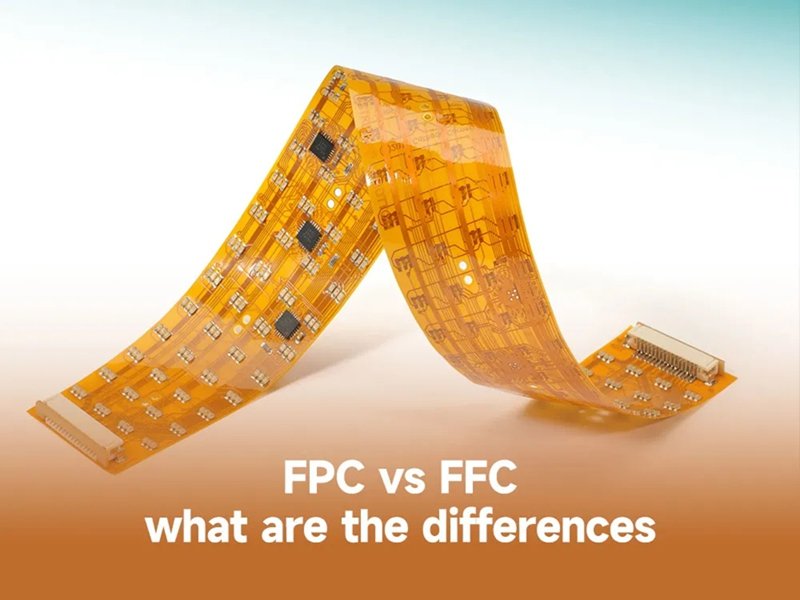
In the world of modern electronics, size, speed, and reliability are no longer just preferences—they are survival requirements. Consumers demand thinner phones, smarter wearables, flexible displays, and medical devices that fit in the palm of your hand. Achieving this means engineers must rethink traditional wiring harnesses, which are too bulky, rigid, and difficult to integrate. Enter FFC (Flat FUses a locking lever to secure the FFC/FPC with minimal force.lexible Cable) and FPC (Flexible Printed Circuit) connectors—two technologies that have revolutionized compact electronic design.
The main difference between FFC and FPC is that FFCs are pre-manufactured flat ribbon cables with parallel conductors, while FPCs are custom-etched flexible circuits that can include complex routing, multiple layers, and even components. FFCs are cheaper and simpler to implement, while FPCs are more versatile, durable, and suitable for high-end or space-constrained applications.
If you’ve ever wondered why your laptop screen folds open thousands of times without the cable snapping, or how your smartwatch can withstand sweat, bending, and charging cycles, the answer lies in these two connector families. This article breaks down every important aspect—from structure and types to costs, customization, and sourcing—so you can confidently decide which solution fits your project best. And as we go, we’ll also show you how a factory like Sino-conn can turn your design into a certified, production-ready assembly.
What are FFC and FPC Connectors?
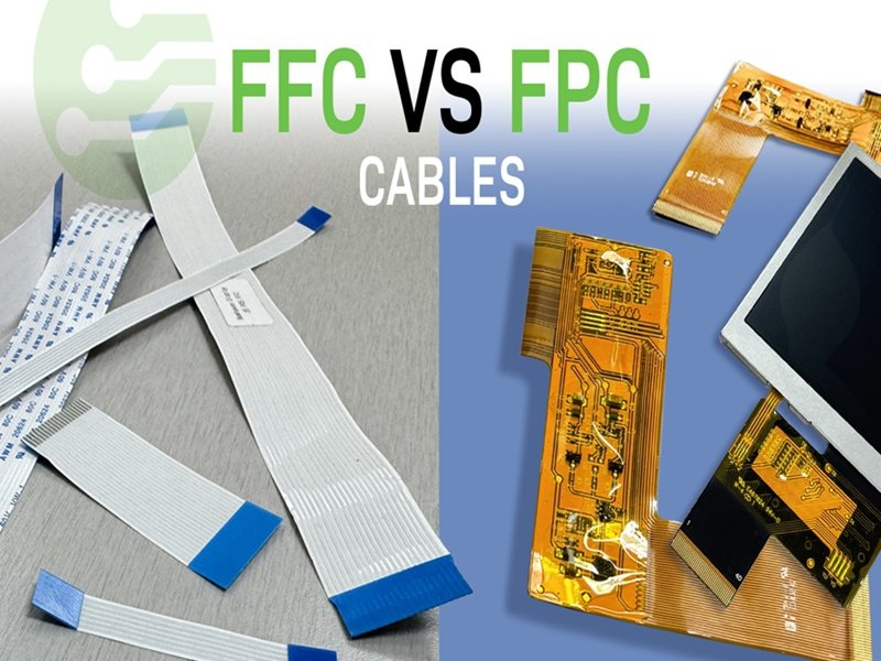
FFC (Flat Flexible Cable) and FPC (Flexible Printed Circuit) connectors are compact, flexible interconnects widely used in modern electronics. FFCs are ribbon-style cables with parallel conductors, offering low cost and easy assembly. FPCs are polyimide-based circuits with etched copper traces, providing advanced flexibility, custom shapes, and higher durability in demanding applications.
What is an FFC (Flat Flexible Cable)?
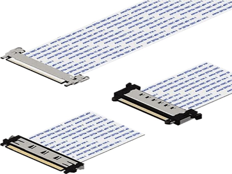
An FFC (Flat Flexible Cable) is a simple, cost-effective connector solution. It consists of flat, thin copper conductors arranged in parallel, laminated between insulating layers like PET or polyimide. The ends are stripped or reinforced with stiffeners to make contact with ZIF (Zero Insertion Force) or LIF (Low Insertion Force) connectors.
Structure and Parts of an FFC
- Conductors: Usually copper (sometimes tin-plated or silver-plated for corrosion resistance).
- Insulation: Polyester (PET) for standard use or Polyimide (PI) for high temperatures.
- Stiffener: Adds rigidity at the connector interface.
- Contacts: Exposed metal ends designed to fit precisely into connectors.
Types of FFC
- Type 1 (A/BD): Contacts on the same side.
- Type 2 (D/AD): Contacts on opposite sides.
- Shielded FFC: EMI-protected version for automotive and industrial use.
- Foldable FFC: Ultra-thin versions for dynamic bending, used in cameras and printers.
Advantages of FFC
- Low cost: Easy to mass-produce with minimal tooling.
- Space saving: Ultra-thin compared to round cables.
- Flexibility: Allows limited bending in compact spaces.
- Fast assembly: Direct insertion into ZIF connectors.
Disadvantages of FFC
- Less durable under repeated bending (dynamic flex).
- Limited customization—straight, parallel conductors only.
- Susceptible to EMI if not shielded.
Common Uses of FFC
- Printers (carriage to controller).
- Laptops (keyboard or LCD screen connections).
- Automotive dashboards and infotainment.
- LED lighting modules.
Typical FFC Parameters
| Parameter | Range/Spec | Notes |
|---|---|---|
| Pitch | 0.3mm – 2.54mm | 0.5mm most common |
| Conductor count | 6 – 80+ | Wider cables = more signals |
| Temperature rating | -40°C to +105°C | High-temp versions up to 150°C |
| Bend cycles | 5k–20k | Limited for moving parts |
| Voltage rating | 30V–200V | Depending on conductor size |
What is an FPC (Flexible Printed Circuit)?
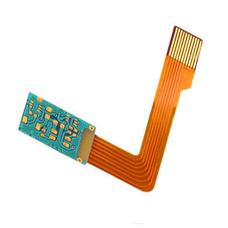
An FPC (Flexible Printed Circuit) is a more advanced interconnect. Instead of prefabricated parallel wires, FPCs use copper foil etched into traces on a polyimide film substrate. This makes them functionally similar to rigid PCBs but with the ability to bend, fold, and twist.
They can be single-layer, double-layer, or multilayer (rigid-flex designs combine rigid PCB sections with flexible connectors). FPCs support high-density interconnects (HDI), impedance-controlled traces, and can integrate components like resistors or sensors directly onto the circuit.
Structure and Parts of an FPC
- Substrate: Polyimide (PI), valued for high heat resistance and flexibility.
- Copper foil: Etched into precise trace patterns for routing.
- Coverlay/Overlay: Protective insulation film for durability.
- Adhesives: Used to bond layers together.
- Stiffeners (optional): Provide mechanical stability at connector ends.
Types of FPC
- Single-layer: One copper layer, basic low-cost applications.
- Double-layer: Two copper layers with vias, better routing.
- Multilayer: 3+ copper layers, used in smartphones and aerospace.
- Rigid-Flex: Combines rigid PCB and flexible layers, used in military and medical devices.
Advantages of FPC
- Extreme flexibility: Can fold and twist, supporting millions of cycles.
- High-density routing: Supports fine pitch (0.2mm or less).
- Lightweight & thin: Reduces weight in aerospace and medical electronics.
- Integration: Can embed resistors, capacitors, or ICs.
Disadvantages of FPC
- Cost: Higher due to etching and lamination process.
- Lead time: Longer compared to FFC.
- Tooling: Requires photolithography and custom masks.
Common Uses of FPC
- Smartphones and foldable devices (hinge assemblies).
- Aerospace wiring harnesses (saves weight and space).
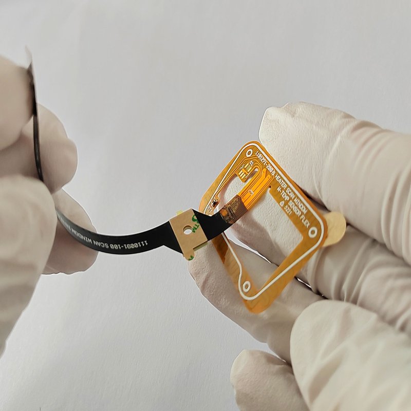
- Medical devices (hearing aids, pacemakers).
- Automotive ADAS systems (cameras, sensors).
Comparison Table: FFC vs FPC
| Feature | FFC (Flat Flexible Cable) | FPC (Flexible Printed Circuit) |
|---|---|---|
| Structure | Parallel copper wires | Etched copper traces on polyimide |
| Flexibility | Moderate (limited bending) | Excellent (folds, twists, dynamic flex) |
| Customization | Limited | Highly customizable (multi-layer) |
| Bend cycles | 5k–20k | 1M+ |
| Cost | Low | Higher |
| Applications | Printers, displays, laptops | Smartphones, aerospace, medical |
Why Do We Need Both FFC and FPC?
- FFC is ideal for simple, standardized connections—low-cost, quick-to-source, and easy to implement.
- FPC is essential when miniaturization, durability, or high-density routing is required.
For example, a TV panel uses FFC to connect its controller to the display (cheap, repeatable). But a foldable smartphone hinge needs an FPC that can bend hundreds of thousands of times without breaking.
Which Types of FFC Connectors Exist?
FFC connectors mainly come in two forms—Type 1 (A or BD) with contacts on the same side, and Type 2 (D or AD) with contacts on opposite sides. Beyond that, variations include shielded, high-temperature, and custom FFCs. Selecting the correct type ensures proper PCB alignment, signal integrity, and long-term reliability.
What are Type 1, Type A, or Type BD FFCs?
Type 1 FFCs—also called Type A or BD—are the most widely used. They have exposed contacts on the same side at both ends. When you insert the cable into two ZIF connectors, the polarity remains consistent because the pins line up identically.
Key Features
- Contacts on the same side → easy orientation.
- Compatible with most ZIF/LIF connectors.
- Lower risk of assembly error.
Advantages
- Widely available, lowest cost.
- Quick assembly in consumer electronics.
- Great for designs where PCB connectors face the same way.
Disadvantages
- Less flexible in layout → not suitable if boards face opposite directions.
Common Use Cases
- Laptop LCD to motherboard connections.
- Printers (carriage cable).
- Automotive infotainment panels.
What are Type 2, Type D, or Type AD FFCs?
Type 2 FFCs—also called Type D or AD—have contacts on opposite sides at each end. This means if you hold the cable flat, one side’s contacts are up while the other side’s contacts are down.
Key Features
- Contacts on opposite sides → polarity flip between ends.
- Designed for compact devices where connectors face in opposite orientations.
Advantages
- Saves space in tight PCB layouts.
- Enables unique board orientations without redesign.
Disadvantages
- Easier to mis-match orientation during prototyping.
- May require more careful assembly checks.
Common Use Cases
- Digital cameras (image sensor to board).
- Smart TVs with compact PCB layouts.
- Wearables, where boards fold in opposite directions.
Beyond Type 1 & Type 2: Other Variations
While Type 1 and Type 2 define contact orientation, FFC connectors can also vary by design enhancements:
- Shielded FFCs: With aluminum foil or braided layers → used in EMI-sensitive environments (automotive, aerospace).
- High-Temperature FFCs: Using polyimide insulation instead of PET → withstands up to 150 °C, used in engine control systems.
- Foldable/Dynamic FFCs: Ultra-thin copper conductors for repetitive bending (scanners, robotics).
- Custom Pitch/Length FFCs: Designed for unique board spacing, often requested by OEMs.
Quick Comparison Table
| Type / Variation | Contact Orientation | Typical Use Case | Advantages | Disadvantages |
|---|---|---|---|---|
| Type 1 (A/BD) | Same side | Laptops, TVs, printers | Easy, low cost | Limited if boards face opposite |
| Type 2 (D/AD) | Opposite sides | Cameras, wearables, small devices | Supports reversed orientation | Higher risk of assembly error |
| Shielded FFC | Same/opp. (varies) | Automotive infotainment | EMI protection | Slightly thicker, costlier |
| High-Temp FFC | Same/opp. (varies) | Engine ECUs, aerospace | Withstands high heat | Costlier than PET versions |
| Dynamic/Foldable FFC | Same/opp. (varies) | Robotics, scanners, folding parts | Survives thousands of bends | More expensive, thinner copper |
How Do Structure and Parameters Differ?
FFC and FPC differ in pitch, thickness, bend radius, and impedance. Pitch defines conductor spacing, thickness affects flexibility, and impedance matters in high-speed designs. Extension cables and ribbon cables provide added versatility in testing and connectivity.
What Does the “Pitch” of an FFC or FPC Mean?
The pitch is the distance between the centers of adjacent conductors. Smaller pitch means higher density but requires more precise connectors.
- Common Pitches: 0.3 mm, 0.5 mm, 1.0 mm, 2.54 mm.
- Impact: Smaller pitch allows compact design but raises cost.
- Example: Smartphones often use 0.3 mm pitch FPCs for tight hinge routing.
Pitch vs. Use Case Table
| Pitch | Typical Use Case | Challenges |
|---|---|---|
| 0.3 mm | Smartphones, cameras | High cost, precise assembly needed |
| 0.5 mm | Laptops, tablets | Balanced cost and density |
| 1.0 mm | Printers, consumer appliances | Easy handling, lower cost |
| 2.54 mm | Industrial equipment, robotics | Large size, less compact |
Are There FPC Extension Cables Available to Extend FPCs?
Yes. FPC extension cables are widely used during prototyping and testing. They allow engineers to connect FPCs without redesigning a PCB.
- Use case: Extending a smartphone display flex for lab measurements.
- Advantage: Saves cost in R&D.
- Disadvantage: Adds extra connectors, which can reduce reliability in mass production.
What is a Ribbon Cable Used For?
A ribbon cable is a flat, multi-conductor cable often used for parallel data transfer. While FFCs are a type of ribbon cable, the term is broader and includes IDC cables used in old PCs and servers.
- Common Uses: Hard drives (IDE cables), legacy computer systems, printers.
- Difference vs FFC: Ribbon cables are thicker, less flexible, and not designed for compact devices.
Which Connector Options Fit Your Design?
Connector choice depends on assembly cycles, space constraints, and board orientation. ZIF connectors provide high durability but cost more, LIF connectors are cheaper for permanent use, top vs. bottom contact ensures proper polarity, and vertical vs. right-angle headers adapt to mechanical design. The right option balances cost, reliability, and size.
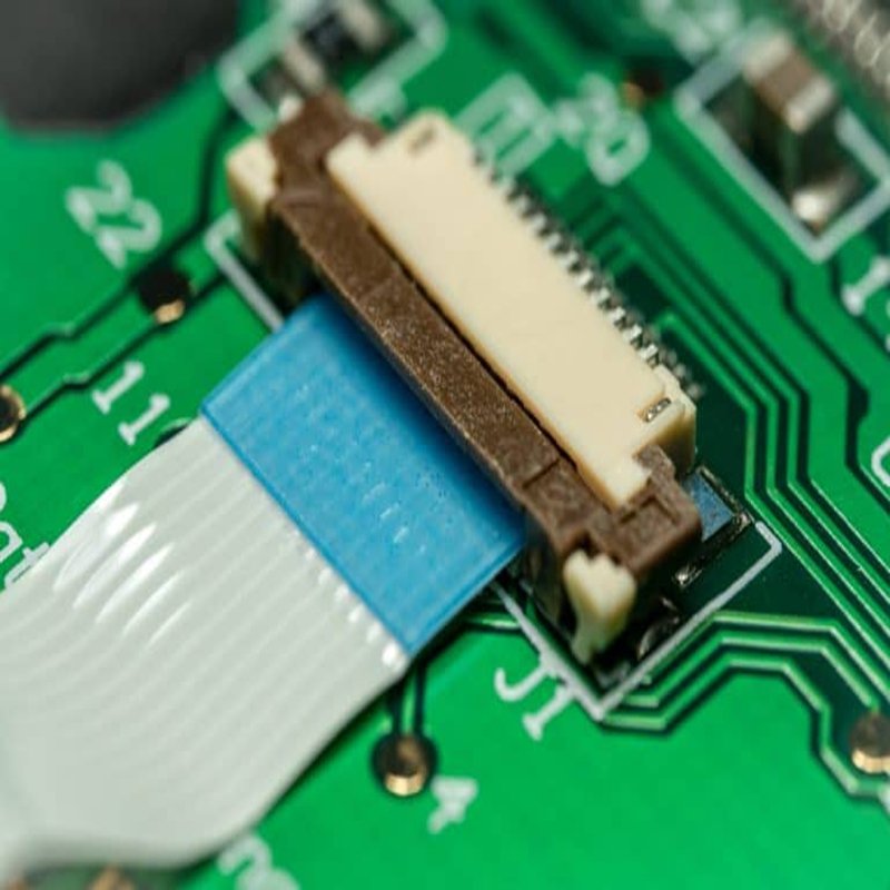
ZIF vs. LIF Connectors
ZIF (Zero Insertion Force):
- Uses a locking lever to secure the FFC/FPC with minimal force.
- Supports 20,000+ mating cycles → ideal for serviceable devices.
- Common Uses: Laptops (LCD flex to motherboard), test equipment, R&D prototypes.
LIF (Low Insertion Force):
- Cable slides in with slight resistance, no locking mechanism.
- Supports ~5,000 mating cycles.
- Common Uses: Consumer goods, cost-sensitive electronics where the cable is not removed often.
Comparison: ZIF vs LIF
| Feature | ZIF Connector | LIF Connector |
|---|---|---|
| Insertion | Zero force, latch secures | Slight friction, no latch |
| Durability | 20,000+ cycles | ~5,000 cycles |
| Cost | Higher | Lower |
| Best for | High-reliability, serviceable | Cost-sensitive, permanent |
| Examples | Laptops, smartphones, testing | Printers, toys, low-cost devices |
Top vs Bottom Contact Orientation
An FFC/FPC cable has exposed conductors on one side. Whether your connector should be top or bottom contact depends on PCB layout and how the cable is inserted.
- Top-Contact Connector: Contacts are on the upper side of the connector. Best when the exposed conductors face upward.
- Bottom-Contact Connector: Contacts are on the lower side. Best when the exposed conductors face downward.
Why it matters:
If you choose the wrong orientation, the cable won’t make electrical contact. In production, this can mean rejected boards and costly redesigns.
Example:
- Laptop keyboard → often uses top-contact connectors because the flex cable contacts face up.
- Smartphone display → may use bottom-contact to reduce vertical stack height.
Top vs Bottom Contact
| Orientation | When to Use | Common Devices |
|---|---|---|
| Top Contact | Cable conductors face up | Laptops, printers, projectors |
| Bottom Contact | Cable conductors face down | Smartphones, cameras, tablets |
Vertical vs Right-Angle Headers
Vertical Connectors:
- Inserted from top-down orientation.
- Best for when height is not limited.
- Simplifies routing in stacked PCBs.
- Example: Test jigs, industrial control boards.
Right-Angle Connectors:
- Inserted horizontally, parallel to the PCB.
- Ideal for slim devices where height is restricted.
- Keeps assemblies compact (e.g., ultrathin laptops, cameras).
- Example: Smartphones, wearables, tablets.
Vertical vs Right-Angle Headers
| Feature | Vertical Header | Right-Angle Header |
|---|---|---|
| Insertion | Top-down | Side-entry |
| Height | Taller stack | Lower profile |
| Use Case | Test boards, industrial devices | Slim electronics, laptops |
| Cost | Usually lower | Slightly higher (precision mold) |
Do EMI and Shielding Impact Performance?
Yes. EMI (Electromagnetic Interference) can degrade FFC and FPC signal quality, especially in high-speed or automotive systems. Shielding—using foil, braided layers, or ground planes—improves performance by reducing noise and crosstalk. Testing methods like TDR and EMC compliance ensure reliable operation in sensitive devices such as medical equipment and 5G smartphones.
Can You Shield an FFC?
Absolutely. FFCs can be manufactured with integrated shielding layers to block EMI. Shielding is critical when cables run near motors, antennas, or other noise sources.
Shielding Methods:
- Aluminum Foil Lamination: Lightweight, low-cost shielding option.
- Braided Copper Shielding: More durable, higher EMI suppression, used in aerospace and automotive.
- Grounded Shield Layer: Provides controlled return paths, reduces common-mode noise.
When to Use Shielded FFCs:
- Automotive infotainment systems (where engine EMI is strong).
- Industrial machinery with motors and high-current switching.
- Medical imaging equipment requiring ultra-low noise.
Standard vs Shielded FFC
| Feature | Standard FFC | Shielded FFC |
|---|---|---|
| EMI Protection | Minimal | Excellent (foil/braid protection) |
| Flexibility | Higher (no extra layer) | Slightly reduced (added thickness) |
| Cost | Lower | +15–25% cost increase |
| Use Case | Consumer electronics | Automotive, aerospace, medical |
How EMI and Crosstalk Are Controlled
Uncontrolled EMI and crosstalk (signals interfering with each other) can ruin performance in high-speed circuits. Engineers mitigate this by:
- Proper Grounding: Adding ground planes or traces in FPCs.
- Controlled Impedance: Matching transmission line impedance for HDMI, USB, LVDS, etc.
- Pitch Adjustment: Increasing spacing between conductors reduces coupling.
- Twisted Signal Pairing (in FPC): Helps balance currents and reduce emissions.
Example:
- In a car’s rear-view camera system, unshielded FFCs caused flickering video during ignition. Switching to shielded FFCs with controlled impedance solved the issue.
Common Signal Integrity Challenges
| Issue | Mitigation Strategy | Example Application |
|---|---|---|
| EMI Noise | Shielding, ground planes | Automotive infotainment, radar |
| Crosstalk | Increased pitch, shielding | Medical ultrasound probes |
| Reflection | Impedance matching, TDR testing | High-speed HDMI or USB cables |
Testing Signal Integrity in High-Speed Applications
To ensure compliance and reliability, FFCs and FPCs undergo signal integrity testing:
- TDR (Time Domain Reflectometry): Measures impedance mismatches along the cable.
- Eye Diagram Testing: Visualizes data clarity at gigabit speeds.
- EMC Testing (Electromagnetic Compatibility): Ensures compliance with CE, FCC, automotive CISPR standards.
- Insertion Loss/Return Loss Tests: Evaluate how much signal is lost or reflected.
Industry Example:
- A 5G smartphone uses ultra-thin 0.3mm pitch FPCs. They must pass eye diagram testing at 10+ Gbps to ensure clean signal transfer to antennas.
How Much Do FFC/FPC Assemblies Cost and How Fast Can You Get Them?
FFC assemblies are generally low-cost, ranging from cents to a few dollars, while FPC assemblies are more expensive due to tooling, customization, and multi-layer builds. Lead times vary: urgent samples can ship in 2–3 days, while bulk orders typically take 2–4 weeks, depending on pitch, shielding, and regional supply chains.
Cost Factors That Influence Pricing
The cost of FFC and FPC assemblies is shaped by design complexity, materials, certifications, and logistics.
For FFCs (Flat Flexible Cables):
- Pitch & Pin Count: Narrower pitch (0.3mm) costs more than 1.0mm; higher conductor count = wider cable = more copper.
- Shielding: Adds 15–25% cost due to foil/braid layers.
- Length: Longer = higher cost (linear material pricing).
- Connector Choice: Genuine branded connectors cost more than substitutes.
For FPCs (Flexible Printed Circuits):
- Layers: Single-layer is cheapest; multi-layer rigid-flex is most expensive.
- Custom Tooling: Masks, etching, and lamination add upfront NRE (Non-Recurring Engineering) costs.
- Impedance Control: High-speed data FPCs require precision manufacturing.
- Volume: Per-piece cost drops significantly in mass production.
Cost Range (Reference Pricing, varies by region & specs):
| Product Type | Prototype Price (per pc) | Mass Production Price (per pc) | Notes |
|---|---|---|---|
| FFC (standard) | $0.20 – $2.00 | $0.05 – $0.50 | Depends on length, pitch |
| FFC (shielded) | $0.50 – $3.00 | $0.20 – $1.00 | Automotive/EMI-sensitive |
| FPC (single-layer) | $1.00 – $5.00 | $0.30 – $1.50 | Consumer electronics |
| FPC (multi-layer) | $5.00 – $20.00 | $1.00 – $6.00 | Smartphones, aerospace |
| Rigid-Flex FPC | $10.00 – $50.00+ | $5.00 – $15.00 | Medical, defense |
Regional and Industry Price Differences
Pricing isn’t uniform worldwide—geography and industry use case both matter.
By Region:
- USA & Western Europe → Higher labor + compliance costs = higher unit prices.
- Japan & Korea → Higher quality expectations, mid-to-high pricing.
- China & Southeast Asia → Lower cost, flexible MOQs, fast lead times.
By Industry:
- Medical & Military → Stricter certifications (UL, ISO13485, MIL-STD), costs ↑ 30–50%.
- Automotive → Shielded, high-temp FFCs → costs ↑ 15–25%.
- Consumer Electronics → High-volume = lowest per-unit cost.
Regional/Industry Pricing Trend
| Factor | Price Impact | Example |
|---|---|---|
| USA vs. Asia | +20–40% in USA | Smartphone OEMs shifting to Asia suppliers |
| Automotive | +15–25% | Shielded FFCs in infotainment |
| Medical/Military | +30–50% | High-reliability rigid-flex |
| Consumer Goods | Lowest cost | Printers, TVs, laptops |
Lead Time Expectations
Lead time depends on urgency, customization, and stock availability.
Standard Lead Times:
- FFC: 2 weeks bulk, 2–5 days sample.
- FPC: 3–4 weeks bulk, 1 week sample.
Urgent Production:
- FFC Samples: As fast as 2–3 days (Sino-conn standard).
- FPC Samples: 5–7 days for simple designs.
Custom Cases:
- Multi-layer FPCs with impedance control may take 4–6 weeks.
- Aerospace/military orders require extended testing & documentation.
Lead Time Guide
| Order Type | FFC Lead Time | FPC Lead Time | Notes |
|---|---|---|---|
| Urgent Samples | 2–3 days | 5–7 days | Premium pricing |
| Standard Samples | 5–7 days | 1–2 weeks | |
| Bulk Production (standard) | 2 weeks | 3–4 weeks | |
| Bulk Production (complex) | 3–4 weeks | 4–6 weeks | Aerospace, military |
How to Source, Customize, and Order From a Reliable Factory?
To source FFC/FPC assemblies, provide clear specs such as dimensions, pitch, current/voltage, bend radius, and compliance needs. Reliable factories like Sino-conn offer CAD drawings within hours, free samples, no MOQ, urgent delivery, and certifications (UL, RoHS, REACH, ISO). Customization covers length, pinout, shielding, materials, and connector types.
What Specs Should You Provide for a Fast Quote?
The first step is giving your supplier the right information. Without it, quotes will be inaccurate or delayed.
Key Specs Buyers Should Provide:
- Basic Dimensions: Cable length, width, pitch, and conductor count.
- Electrical Ratings: Voltage, current capacity, and impedance requirements.
- Environmental Conditions: Operating temperature, exposure to oil, UV, chemicals, or vibration.
- Bending Requirements: Number of expected flex cycles (e.g., 20k vs. 1M).
- Compliance Needs: RoHS, REACH, halogen-free, PFAS-free, flame rating.
- Connector Details: ZIF/LIF, top/bottom contact, brand preference (original vs. substitute).
Sample Specification Request Table
| Spec Category | Example Input | Why It Matters |
|---|---|---|
| Pitch | 0.5mm | Defines connector compatibility |
| Length | 150mm | Determines material cost |
| Conductor Count | 20 pins | Impacts width |
| Voltage/Current | 50V / 0.5A | Prevents overheating |
| Bend Cycles | 100,000 (dynamic hinge) | Ensures reliability |
| Compliance | RoHS, UL, halogen-free | Industry certification |
How Flexible is Customization?
Unlike off-the-shelf parts, FFC/FPC assemblies can be highly customized:
- Length & Width: Can range from a few millimeters to over a meter.
- Pinout Definition: Straight-through, crossed, or custom mapping.
- Shielding Options: Foil, braid, or ground plane integration.
- Materials: PET vs. PI insulation, standard vs. high-temp adhesives.
- Connector Choice: Original branded connectors (e.g., Hirose, Molex) or cost-effective substitutes.
- Form Factor Adjustments: Curved FPC shapes, folded routing paths.
Example:
- A medical OEM requested a halogen-free, biocompatible FPC with 200k bending cycles.
- Custom material sourcing and impedance-controlled traces ensured compliance + durability, making mass adoption feasible.
How Quickly Can Samples and Mass Orders Ship?
One of the strongest differentiators between suppliers is lead time.
At Sino-conn:
- CAD Drawings: Delivered in 30 minutes – 3 days (average same-day).
- Samples:
- Urgent: 2–3 days.
- Standard: 1–2 weeks.
- Mass Production:
- Standard: 2–4 weeks.
- Urgent: as fast as 2 weeks for bulk.
Lead Time Comparison
| Stage | Standard Lead Time | Urgent Lead Time | Notes |
|---|---|---|---|
| CAD Drawing | 1–3 days | 30 minutes–1 day | Free with inquiry |
| Sample Production | 1–2 weeks | 2–3 days | MOQ = 1 pc |
| Mass Production | 3–4 weeks | 2 weeks | Depends on order size |
Which Certifications Ensure Quality and Compliance?
Buyers—especially in medical, aerospace, automotive, and consumer electronics—must ensure suppliers meet strict standards.
Sino-conn Certifications & Quality Control:
- UL & ISO9001 / ISO14001: Safety and environmental compliance.
- RoHS & REACH: Chemical restriction compliance (EU).
- PFAS-Free & Halogen-Free Options: For eco-sensitive industries.
- COC & COO Documents: For international trade and customs clearance.
- 3-Step Inspection:
- In-process QC (while cables are being produced).
- Finished product QC (before packaging).
- Pre-shipment QC (final check for defects).

Why This Matters:
- Prevents costly field failures.
- Ensures products can be legally sold worldwide.
- Protects OEM brand reputation.
Conclusion
Sourcing FFC/FPC connectors is not just about price—it’s about accuracy, speed, and reliability. A good supplier reduces design risks, accelerates prototyping, and ensures compliance with global standards.
Looking for custom FFC or FPC connectors? Contact Sino-conn today for a free consultation, CAD drawing, and fast quotation.