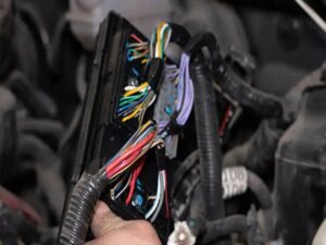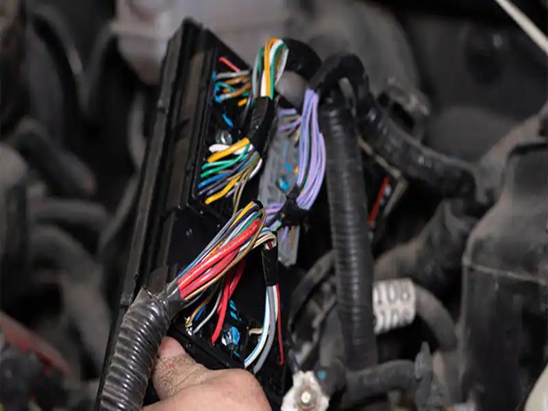
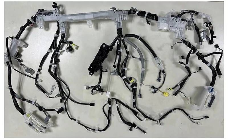
A car or industrial machine may have hundreds of wires hidden under panels and bundled into harnesses. These networks deliver power and data across every component. If one wire fails—whether due to heat, vibration, or aging—the system may misfire, lights could flicker, or safety systems might shut down. That’s why testing a wiring harness is one of the most crucial steps in both production and maintenance.
You can test a wiring harness using tools like multimeters, continuity testers, or dedicated harness analyzers. Start by inspecting for visible damage, then run continuity and resistance tests to confirm each wire is intact. Voltage drop tests help identify weak connections, while OEM or ISO standards guide compliance checks. Testing ensures harnesses are safe, reliable, and compliant with international standards before installation or mass production.
Imagine an engineer sourcing a replacement harness for an EV fleet. The supplier skips proper high-voltage testing, and the orange cable meant to carry 400 volts overheats under load. Within weeks, vehicles stall and face recall. That mistake costs millions—but could have been avoided with thorough harness testing. Keep reading, and you’ll see how to test wiring harnesses correctly, from tools and procedures to global compliance.
What Is Wiring Harness Testing?
Wiring harness testing is the process of verifying the functionality, safety, and durability of all wires, connectors, and circuits in a harness. It ensures correct continuity, resistance, and voltage handling while preventing shorts or open circuits. Proper testing matters because harnesses are critical to power delivery and signal integrity in vehicles, aerospace, medical, and industrial systems. Without testing, risks include malfunctions, costly recalls, safety hazards, and compliance failures in regulated markets. A wiring harness is often compared to the nervous system of a machine. Just as nerves carry signals across the human body, wiring harnesses deliver power and data between every electronic component. If one connection is wrong, or a single wire is defective, the impact can range from a flickering dashboard light to a catastrophic safety failure in braking or medical equipment. That’s why testing wiring harnesses is not optional—it’s an essential quality assurance step in both production and maintenance.
- The Purpose of Testing Harness testing ensures that each circuit is complete, functional, and safe. The most basic test, continuity, checks whether electricity can flow without interruption. Voltage and resistance tests confirm that wires can carry the correct load without overheating or dropping current. Advanced tests measure insulation resistance to detect leakage and dielectric strength to ensure wires don’t fail under stress. Ultimately, testing verifies that the harness will perform exactly as designed under real-world conditions.
- Risks of Skipping Testing
Skipping tests often leads to:
- Short circuits that blow fuses or damage ECUs
- Voltage drops that reduce performance in lights or motors
- Electromagnetic interference (EMI) affecting data lines
- Fire hazards from overheated wires
Industry data shows that 30–40% of automotive recalls involve electrical issues, many traced back to wiring harness defects.
- Signs of a Failing Wiring Harness
Even without lab tools, failures reveal themselves:
- Flickering lights or dashboard errors
- Unresponsive sensors or intermittent signals
- Melted insulation or burnt smells
- Blown fuses repeating frequently
- Industry-Specific Importance
Different sectors have different stakes:
- Automotive: Ensures ADAS, airbags, and engine control units function reliably.
- Aerospace: Harnesses face vibration, altitude, and EMI; testing is mission-critical.
- Medical devices: Patient-monitoring harnesses must survive sterilization cycles without insulation failure.
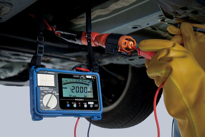
- EV and hybrid systems: High-voltage orange cables require dielectric withstand tests to meet ISO and SAE safety regulations.
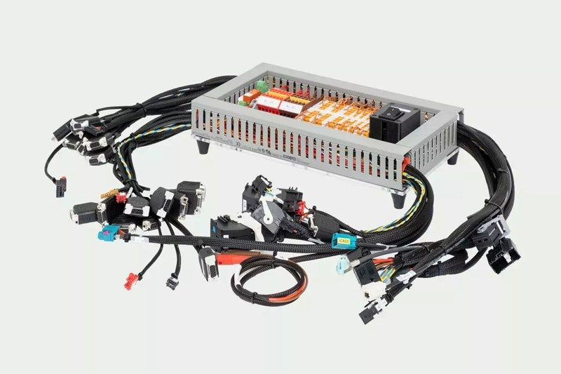
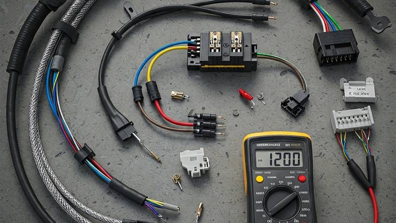
Which Tools Are Commonly Used to Test a Wiring Harness?
Common tools for wiring harness testing include multimeters for continuity and voltage checks, test lamps for quick diagnostics, and harness analyzers for full pin-to-pin validation. Advanced industries also use simulation software and automated test benches to check EMI shielding, resistance, and current handling under load. Selecting the right tool depends on application—basic repairs need multimeters, while OEM production requires automated testers.
Harness testing tools range from handheld devices to complex automated systems.
1. Multimeters & Continuity Testers
The digital multimeter (DMM) is the most widely used tool across workshops and engineering labs. It can measure:
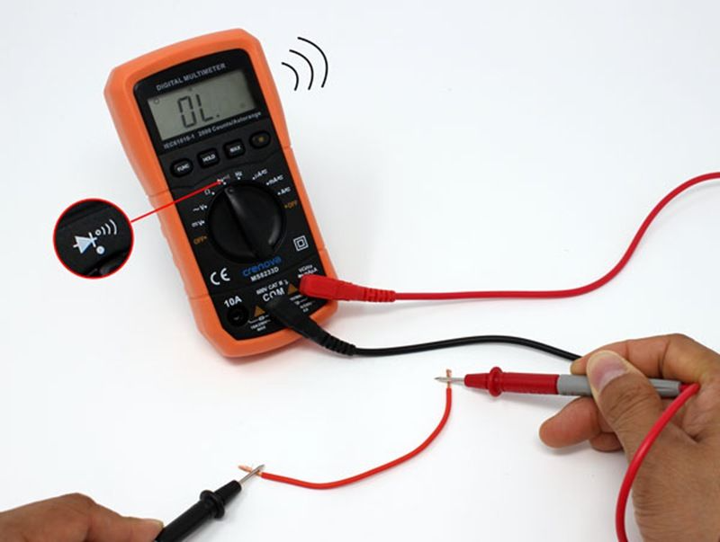
- Continuity: Verifies if a wire is intact end-to-end.
- Resistance: Detects partial breaks or high resistance in circuits.
- Voltage: Confirms proper voltage delivery under load.
Why it’s useful:
- Affordable and portable.
- Perfect for quick checks and small-batch testing.
- Works for both automotive and industrial harnesses.
Limitations:
- Time-consuming for large harnesses with many pins.
- Requires manual operation, so prone to human error.
2. Test Lamps
A simple 12V/24V test light helps technicians verify if a circuit has live power.
- Useful for checking fuses, relays, and simple connections.
- Ideal for roadside or on-site maintenance.
Limitations:
- Cannot measure resistance or detect subtle voltage drops.
- Not suitable for precision or compliance testing.
3. Harness Test Benches & Analyzers
- Used in OEM factories and certified labs.
- Validate entire harnesses with thousands of circuits.
- Test pin-to-pin connections, resistance, cross-talk, and EMI shielding.
- Offer data logging and automated reporting.
4. Automated Test Benches
Advanced industries like automotive OEMs, aerospace, and defense rely on automated harness test benches. These systems:
- Apply load and simulate real-world current/voltage stress.
- Test insulation resistance and dielectric strength.
- Integrate with CAD/PDF diagrams for automated mapping.
- Generate certification-ready reports.
Example: An aerospace harness may undergo altitude simulation, vibration resistance, and EMI shielding tests on a test bench before approval.
5. Simulation & Virtual Testing Software
Increasingly, engineers use digital simulation tools to test harness designs before physical production.
- Predicts performance under thermal, electrical, and mechanical stress.
- Saves time during R&D.
- Reduces prototyping costs by identifying flaws early.
6. Supplier-Provided Test Fixtures
Suppliers like Sino-conn also provide:
- Custom test fixtures built around your harness design.
- CAD/PDF pin-out diagrams for testing accuracy.
- Rapid 2–3 day sample harnesses for physical testing before bulk orders.
Comparison Table: Tools vs Applications
| Tool / Method | Best For | Accuracy | Cost Level |
|---|---|---|---|
| Multimeter | Small repairs, field work | Medium | Low |
| Test Lamp | Quick checks | Low | Low |
| Harness Analyzer | OEM production, QC labs | High | High |
| Simulation Software | R&D, prototyping | High | Medium |
How Do You Perform a Basic Continuity and Voltage Test?
To test a wiring harness, first de-energize the circuit and disconnect the harness. Use a multimeter in continuity/ohms mode to confirm each pin-to-pin path is intact and that there are no shorts between unrelated pins or to ground. Then re-energize and measure DC voltage and voltage drop under load at key points (source, connector, load). Compare readings against specs or expected values by wire gauge/length. Document results in a test log before reassembly.
Tools & Safety
- Digital multimeter (DMM) with continuity/ohms & DCV ranges
- Back-probe pins / fine probes, test leads, alligator clips
- Service manual or pin-out/CAD/PDF drawing (from OEM or supplier)
- Power supply or vehicle battery (for voltage tests)
- Insulation gloves & eye protection; lockout/tagout if applicable
Never probe orange high-voltage EV cables unless you’re HV-qualified and following OEM EV procedures.
Step A — Preparation & Isolation
- Identify the harness: Get the pin-out and color map. Label connectors (C101, C102…).
- De-energize: Key off, disconnect battery/PSU. Wait for modules to sleep (typically 2–5 minutes).
- Isolate the harness: Unplug both ends so you’re measuring only the harness, not downstream electronics.
- Inspect visually: Look for chafing, melted insulation, bent pins, moisture, green corrosion. Note any damage.
Step B — Meter Setup & Lead Zero
- Set the DMM to continuity (beep) or Ω.
- Short the meter leads together to note lead resistance (often 0.02–0.10 Ω).
- If your meter supports it, REL/Zero the reading so the display subtracts lead resistance.
Step C — Pin-to-Pin Continuity (is the path intact?)
- From the drawing, pick a circuit (e.g., C101-Pin 3 → C205-Pin 7).
- Place one probe on the first pin, the other on the target pin.
- Pass: Beep (continuity) or low resistance close to R_expected (see table below).
- Fail: No beep / “OL” = open circuit (broken conductor, bad crimp, mis-pinned).
- Log the result (see log template).
Step D — Short-to-Short & Short-to-Ground Checks
- Adjacent/Unrelated pins: Measure between the tested wire and neighboring pins.
- Pass: “OL” (no continuity).
- Fail: Any continuity = short/cross-talk.
- Short to ground/chassis: Measure between the circuit wire and the harness ground shell or connector shield.
- Pass: “OL” (unless the circuit is intentionally grounded).
- Fail: Continuity = insulation fault.
Step E — Resistance Reality Check (optional but useful)
- With the harness still isolated, read the ohms end-to-end.
- Compare to expected copper resistance for the gauge & length + small contact resistance:
| Copper wire (typical) | Ω per meter (one conductor) |
|---|---|
| 22 AWG | ~0.053 Ω/m |
| 20 AWG | ~0.033 Ω/m |
| 18 AWG | ~0.021 Ω/m |
| 16 AWG | ~0.013 Ω/m |
| 14 AWG | ~0.008 Ω/m |
Rule of thumb: Short harness runs (≤1 m, 18–22 AWG) typically read ≤0.3 Ω end-to-end. Add ~0.01–0.05 Ω for two contacts. Significantly higher values suggest corrosion, broken strands, or poor crimps.
Step F — Re-Energize for Voltage & Voltage-Drop
Now you’re measuring performance in operation.
- Reconnect the harness. Restore power (key ON or bench PSU).
- Source voltage: Measure at the feed (e.g., battery → fuse output). Confirm nominal 12–14.4 V (or 24–28 V for trucks).
- At the load: With the circuit ON and under normal load, measure DCV at the device input.
- Voltage-drop across connectors:
- Probe on the same wire, one lead before a connector, the other after it.
- Pass: Ideally ≤0.10–0.20 V drop across a good connector at typical load.
- Fail: >0.20–0.30 V suggests high resistance (burnt pin, loose crimp, oxidation).
- Voltage-drop along a wire segment:
- Probe at segment start and end while loaded.
- For most 12 V circuits, keep total circuit drop (feed + return) <0.5 V; critical modules may require <0.2–0.3 V.
- Ground path test:
- Measure between device ground and battery negative while loaded.
- Pass: ≤0.10–0.20 V. Higher indicates ground resistance (bad ground lug, paint, corrosion).
Step G — Quick Pass/Fail Guide
| Test | Pass (typical) | Fail (action) |
|---|---|---|
| Continuity (pin-to-pin) | Beep / Low Ω near expected | “OL” → open; repin/repair conductor |
| Short-to-short | “OL” to unrelated pins | Any Ω/beep → locate insulation damage |
| Short-to-ground | “OL” (unless designed to ground) | Ω/beep → trace to chafe point |
| Connector drop (loaded) | ≤0.10–0.20 V | >0.20–0.30 V → clean/replace crimp/pin |
| Wire segment drop (loaded) | Small, scales with length/gauge | Large → damaged strands/undersized wire |
| Ground drop (loaded) | ≤0.10–0.20 V | >0.20–0.30 V → service ground points |
Step H — Troubleshooting Tips
- High drop only under load → suspect loose crimp, corroded pin, or broken strands.
- Intermittent continuity → flex the harness while metering; look for fatigue near bend radii.
- Multiple pins affected → check shared splices or ground blocks.
- Repeat fuse blows → isolate branches; perform short-to-ground on each branch.
Step I — Minimal Test Log
| Circuit | From Pin → To Pin | Cont.? | Ω | V @ Load | V-drop Conn | V-drop GND | Result | Notes |
|---|---|---|---|---|---|---|---|---|
| IGN feed | C101-3 → C205-7 | Yes | 0.09 | 12.2 | 0.06 | 0.04 | Pass | Cleaned C205 pin |
| Sensor 5V | ECU-12 → SENS-2 | Yes | 0.11 | 5.01 | 0.02 | 0.01 | Pass | — |
Do Different Industries Require Specific Wiring Harness Tests?
Yes, industries require different harness tests. Automotive harnesses undergo vibration and thermal cycling tests; aerospace adds EMI and altitude simulations; medical requires biocompatibility and sterilization tolerance; EV/high-voltage harnesses face dielectric and insulation resistance checks. Each industry sets unique standards to ensure safety and reliability under specific environments.
- Automotive
- Continuity, vibration, temperature cycling.
- EMI testing for infotainment and ADAS.
- Aerospace
- Extreme vibration + altitude chamber tests.
- EMI and lightning strike simulations.
- Medical Devices
- Sterilization resistance.
- Biocompatible insulation materials.
- Military & Defense
- Flame resistance, salt fog, extreme durability.
- High-Voltage EV Harnesses
- Dielectric withstand tests.
- Orange insulation verification.
Case Example:
A German EV OEM required high-voltage harnesses tested for 1000V insulation resistance. Sino-conn delivered samples in 3 days, passed tests, and won bulk order production.
Is There a Standard for Wiring Harness Testing Across Countries?
There is no single global standard for wiring harness testing, but most countries follow recognized frameworks like ISO 6722, SAE J1128, JIS C3406, and China’s GB/T 12528. These define conductor sizes, insulation performance, and testing methods for continuity, voltage, resistance, and durability. Compliance with UL, RoHS, REACH, and PFAS-free requirements is often required for export. For global projects, suppliers must tailor testing to the target region’s regulations to ensure safety, reliability, and legal approval.
When sourcing or producing wiring harnesses, one of the most common questions engineers and procurement teams face is: “Which standard should this harness comply with?” Unfortunately, the answer isn’t simple — because standards differ by country and industry, and there’s no universal framework that all regions have adopted. Instead, buyers and suppliers must work within overlapping but distinct systems.
1. Global Core Standards
- ISO 6722 (Europe/Asia): Covers low-voltage cables up to 60V DC and high-voltage up to 600V, focusing on conductor dimensions, insulation performance, and thermal endurance. Widely used in EU automotive and industrial harnesses.
- SAE J1128 (North America): Governs primary automotive wire in 12V and 24V systems, including temperature ranges, chemical resistance, and voltage drop criteria. Standard in the US and Canada.
- JIS C3406 (Japan): Specifies conductor sizes, insulation thickness, and resistance requirements for automotive wiring. Frequently referenced by Japanese OEMs such as Toyota, Honda, and Nissan.
- GB/T 12528 (China): Defines automotive low-voltage cable performance, similar to ISO 6722 but localized for Chinese manufacturing and regulatory systems.
- UL Standards (Global): Common for flame resistance, insulation integrity, and safety in export markets.
2. Regional Differences That Matter
While the core focus of each standard is similar — ensuring wires don’t overheat, short, or degrade under stress — regional variations create challenges:
- Conductor size notation: Metric vs AWG (American Wire Gauge).
- Temperature classes: SAE may allow higher ranges for engine bay wires than JIS.
- Environmental tests: ISO emphasizes UV and oil resistance for outdoor applications; GB/T may prioritize humidity and salt-spray resistance for coastal environments.
- Certification expectations: The EU requires RoHS/REACH compliance; North America leans on UL listings; Japan enforces JIS with strict OEM approval processes.
3. Material & Safety Compliance
Beyond electrical standards, environmental and safety certifications are now equally critical:
- RoHS (Restriction of Hazardous Substances): Restricts lead, cadmium, and other harmful materials.
- REACH (Registration, Evaluation, Authorization, and Restriction of Chemicals): EU regulation ensuring safe chemical use.
- PFAS-free, Halogen-free, Non-Fluorine: Growing demand in EU, US, and Japan due to fire safety and environmental concerns.
- COC/COO (Certificates of Conformity/Origin): Frequently requested for customs clearance and OEM procurement.
Wiring Harness Standards by Region
| Region / Country | Primary Standard(s) | Focus Areas | Common Applications |
|---|---|---|---|
| USA / Canada | SAE J1128, UL | AWG sizes, high-temp, chemical resistance | Automotive, trucks |
| EU / UK | ISO 6722, VDE | UV, oil, high-voltage EV | Cars, EVs, machinery |
| Japan | JIS C3406 | Conductor precision, OEM requirements | Automotive, electronics |
| China | GB/T 12528 | Local compliance, humidity resistance | Domestic vehicles |
| Global Exports | UL, RoHS, REACH | Flame resistance, environmental safety | OEM supply chains |
Conclusion
Testing a wiring harness is more than a routine checklist — it’s a safeguard for safety, reliability, and compliance. From simple continuity checks with a multimeter to advanced automated testing benches, every step ensures that wires deliver the right power, signals, and durability under real-world conditions. Skipping or simplifying this process can lead to costly downtime, warranty claims, or even life-threatening failures in automotive, aerospace, or medical applications.
Whether you are an R&D engineer validating a prototype, an OEM factory sourcing high-volume harnesses, or a trade buyer looking for reliable partners, Sino-conn ensures your wiring harnesses are tested, certified, and ready to perform.
Contact Sino-conn today to discuss your project, request a quote, or schedule a sample. Let us help you design and deliver wiring harness solutions that meet the highest standards of safety and performance — with the flexibility and speed your business needs.