Skip to content
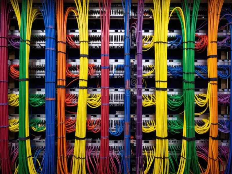
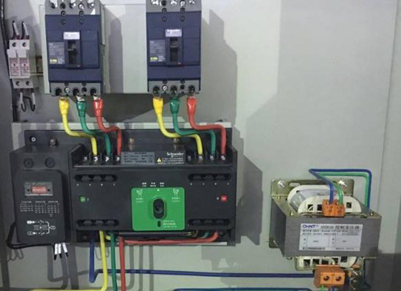
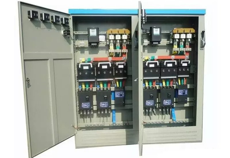
Have you ever opened an electrical cabinet or network rack and felt overwhelmed by the rainbow of wires inside? For engineers, electricians, and data center managers, cable color codes are the secret language that keeps complex systems safe, efficient, and easy to troubleshoot.
Cable color codes assign specific colors to wires in electrical, data, and control systems to indicate their function—such as power, ground, or signal. Different regions follow standards like NEC (North America) or IEC (Europe) to ensure safety, prevent wiring errors, and simplify maintenance. By using standard or custom color codes, technicians can install, inspect, and repair systems quickly and reliably.
Before we dive deep, imagine this: A telecom facility installs 5,000 Ethernet lines in six months without color coding. A single connection failure takes 10 hours to trace. After adopting a simple blue-yellow-red system, the same failure is fixed in 20 minutes. That’s the power of cable color coding in action.
What Are Cable Color Codes and How Are They Used?
Cable color codes assign specific insulation colors to wires for quick identification of their purpose—such as live power, neutral return, ground, or signal transmission. Used in electrical, data, and control systems, they ensure safety, prevent wiring errors, speed up installation, and simplify troubleshooting across residential, commercial, and industrial applications worldwide.
A Complete Guide to Cable Color Codes
Cable color codes might look simple—just colors on insulation—but in reality, they form a universal visual language for electrical and electronic systems. Whether it’s a three-wire home circuit or a 5,000-node data center, standardized colors prevent confusion, save hours in maintenance, and ensure compliance with safety regulations.
Let’s break this down step by step:
Core Purposes of Cable Color Codes
Cable color codes serve four primary functions:
- Safety and Risk Reduction
- Live (phase) wires carry dangerous voltage. A standardized color prevents accidental contact during installation or repair.
- Ground wires provide a safe path for fault current—color coding ensures they’re never confused with live or neutral conductors.
- Example: In North America, green or green-yellow is always ground; black or red is live.
- Quick Circuit Identification
- In complex systems, electricians and technicians need to distinguish between power, control, and signal circuits instantly.
- Color codes let them visually trace wiring instead of relying solely on labels or schematics.
- Standardization for Compliance
- Global standards like NEC, IEC, and ANSI/TIA require or recommend specific colors to ensure interoperability and safety across industries.
- Insurance and regulatory inspections often check for proper wire color coding.
- Faster Installation and Maintenance
- Predefined colors reduce human error, allowing less-experienced workers to install systems correctly with minimal training.
Where Cable Color Codes Are Used
| Application Area | Purpose of Color Coding | Example Colors (Typical) |
|---|---|---|
| Residential Wiring | Power circuits for lighting, outlets, HVAC | Black (line), White (neutral), Green (ground) |
| Commercial Buildings | Power, lighting, elevators, security circuits | Red, Blue, Yellow (3-phase power) |
| Industrial Automation | Control panels, PLC wiring, sensors, actuators | Orange (control), Blue (24V DC), Gray (signal) |
| Data Centers & IT | Ethernet, fiber optic, PoE, VoIP, server connections | Blue (LAN), Yellow (PoE), Red (VoIP) |
| Transportation & Marine | Navigation lights, bilge pumps, communication, engine control | Red (power), Black (ground), Yellow (auxiliary) |
| Aerospace & Defense | Avionics, military communication, classified data separation | Yellow (Top Secret), Red (Sensitive) |
Real-World Example: Data Center Cabling Chaos vs Color Coding
- Before: A data center in Chicago had over 15,000 Ethernet cables but no color coding scheme. Tracing a single faulty PoE line took 10 hours and required shutting down multiple racks.
- After: Adopting a simple scheme—blue for LAN, yellow for PoE, red for VoIP—reduced troubleshooting time by 85% and prevented downtime costs exceeding $100,000 annually.
Typical Functions Assigned to Colors
| Color | Common Meaning Across Applications | Notes |
|---|---|---|
| Black/Red | Live or phase conductor (power) | NEC uses black for single-phase, red for Line 2 |
| White/Gray | Neutral (return path) | Carries current back to source |
| Green/Green-Yellow | Ground or earth connection | Safety path for fault current |
| Blue | Data signal or low-voltage control | Common in network cabling |
| Yellow | Power over Ethernet (PoE), alarm circuits | IT and security systems |
| Orange | Interlock circuits, industrial control signals | Often in automation systems |
Note: Always check local or regional standards—meanings can differ by country or industry.
Benefits Beyond Identification
- Improved Aesthetics & Organization
- Structured cabling projects often use colors for visual orderliness in racks and panels, boosting professionalism and safety audits.
- Cross-Department Communication
- Electricians, IT staff, and safety inspectors all understand the same color scheme, reducing handover errors between teams.
- Documentation & Training
- Standardized colors make it easier to create accurate wiring diagrams and train new technicians quickly.
Consequences of Ignoring Color Codes
- Safety Hazards: Misidentifying a live conductor can cause shocks, fires, or equipment damage.
- Regulatory Violations: Non-compliance with NEC or IEC can lead to fines or project rejection during inspections.
- Maintenance Delays: Technicians may spend hours tracing undocumented wires, increasing downtime.
Case Study: Manufacturing Plant Compliance Upgrade
A U.S. manufacturing facility upgraded from mixed-color random wiring to NEC-compliant colors for its 3-phase 480V circuits:
- Black, Red, Blue for phases
- White for neutral
- Green for ground
Result: 30% reduction in maintenance time and full OSHA compliance during safety audits.
Cable Color Codes in Documentation & CAD Systems
Modern CAD tools like AutoCAD Electrical and EPLAN now include:
- Predefined color layers for power, control, and signal circuits
- Automatic BOM generation listing cable colors for procurement
- Easy cross-referencing between schematics and physical wiring
This integration ensures color coding moves beyond physical installation to full lifecycle management.
International Complexity: Why One Color Doesn’t Fit All
- In the U.S., white = neutral, but in IEC systems, blue = neutral.
- Older European installations sometimes used black = neutral, creating hazards during retrofits.
- Multi-national projects require color adaptation tables to prevent mistakes when importing equipment.
Example: A German-made CNC machine installed in Texas required rewiring its control panel to match U.S. NEC standards before commissioning.
Which International and Regional Standards Exist for Cable Colors?
Cable color standards vary worldwide. The U.S. follows NEC, Europe uses IEC, while Asia-Pacific adopts hybrid or IEC-based practices. Telecommunications rely on ANSI/TIA-606-B, and specialized sectors like military or marine have unique codes. Understanding regional standards prevents wiring errors, ensures compliance, and streamlines global project integration.
Global Cable Color Standards Explained
When you design, install, or maintain electrical and data systems across different countries or industries, cable color standards become critical. Using the wrong color for a live conductor or signal cable can lead to:
- Safety hazards (e.g., shocks, fires)
- Regulatory violations during inspections
- Costly rework for exported machinery or global projects
Let’s break this down by region, standard, and real-world usage.
North America: NEC and CEC Standards
The National Electrical Code (NEC) in the U.S. and the Canadian Electrical Code (CEC) govern most wiring practices in North America. These standards are widely adopted in commercial, residential, and industrial installations.
| Function | Typical NEC/CEC Color | Notes and Usage Examples |
|---|---|---|
| Ground / Earth | Green, Green-Yellow, or Bare | Always reserved for grounding, never used for current-carrying |
| Neutral | White or Gray | Return conductor for AC circuits |
| Hot / Phase 1 (Single Phase) | Black | Standard line conductor |
| Hot / Phase 2 (3-Phase) | Red | Second phase in 3-phase circuits |
| Hot / Phase 3 (3-Phase) | Blue | Third phase in 3-phase circuits |
Example: A U.S.-based OEM exporting industrial machines to Europe must convert black-white-green wiring to brown-blue-green/yellow to meet IEC norms before CE marking.
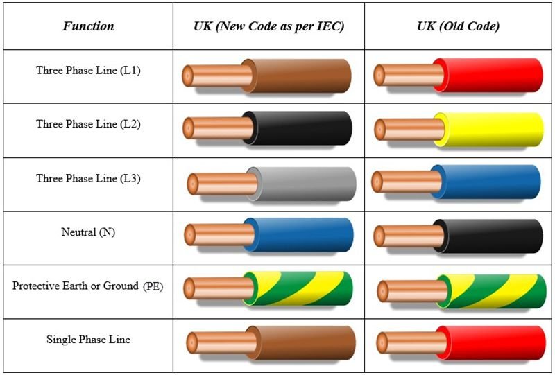
Europe: IEC 60446 and Harmonized Colors
The IEC 60446 standard applies to most European Union countries and many regions adopting IEC-based practices (e.g., Asia, Africa, Middle East).
| Function | IEC Color Code (Typical) | Common Applications |
|---|---|---|
| Protective Earth (PE) | Green-Yellow | Grounding and bonding systems |
| Neutral (N) | Blue | Return conductor in AC circuits |
| Line 1 (L1) | Brown | Single-phase live wire |
| Line 2 (L2) | Black | Second phase in 3-phase systems |
| Line 3 (L3) | Gray | Third phase in 3-phase systems |
Key Difference vs NEC:
- NEC uses black/red/blue for phases, while IEC uses brown/black/gray.
- Neutral in NEC = White; Neutral in IEC = Blue.
This difference is a top cause of wiring errors when retrofitting U.S. equipment in Europe.
Asia-Pacific and Middle East Practices
Many Asian countries follow IEC colors but with some legacy differences:
- India (older systems): Red-Yellow-Blue phases instead of Brown-Black-Gray.
- Japan: Historically used black = neutral, now aligning with IEC Blue.
- Middle East: IEC colors with Arabic labeling for compliance.
Tip for Global Projects: Always request as-built wiring diagrams with color tables when importing/exporting machinery to avoid costly rewiring.
Telecommunications: ANSI/TIA-606-B and ISO/IEC 11801
For structured cabling systems (Ethernet, fiber optics, PoE), electrical color codes are insufficient. Standards like ANSI/TIA-606-B in the U.S. and ISO/IEC 11801 globally cover:
- Cable labeling requirements
- Recommended (but not enforced) color codes for patch panels and horizontal cabling
Common Data Cable Colors
| Color | Typical Use |
|---|---|
| Blue | Data / LAN connections |
| Yellow | Power over Ethernet (PoE) |
| Red | Critical systems (VoIP, security) |
| Green | Crossover or test connections |
| Orange | Demarcation points / ISP handoff |
Many data centers adopt internal standards for cable colors to simplify troubleshooting and documentation.
Specialized Sectors: Military, Marine, and Aerospace
Military (U.S. DoD):
- Yellow = Top Secret data
- Red = Secret / Sensitive circuits
- Blue = Unclassified systems
Marine Wiring (ABYC Standards):
- Red = DC Positive
- Yellow = DC Negative (new standard)
- Black = DC Negative (older standard)
Aerospace (AS50881):
- Color coding combines phase marking + function marking for multi-core harnesses in aircraft systems.
Harmonization Efforts and Challenges
Organizations like IEC, IEEE, and CENELEC are pushing for global harmonization to reduce wiring confusion in international projects.
Challenges include:
- Legacy infrastructure with old color codes
- Resistance from industries with unique safety requirements
- Cost implications of changing documentation, training, and stock materials
Example: The EU required all member states to adopt brown/blue/green-yellow for single-phase wiring post-2006. Retrofitting older buildings remains an ongoing process.
Comparison Table: NEC vs IEC vs Telecom Standards
| Function | NEC (U.S.) | IEC (Europe) | Telecom / Data |
|---|---|---|---|
| Ground/Earth | Green / Green-Yellow | Green-Yellow | Not Applicable |
| Neutral | White / Gray | Blue | Not Applicable |
| Line 1 (L1) | Black | Brown | Blue (Data) |
| Line 2 (L2) | Red | Black | Yellow (PoE) |
| Line 3 (L3) | Blue | Gray | Red (Critical Systems) |
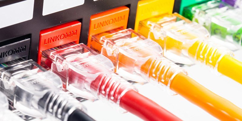
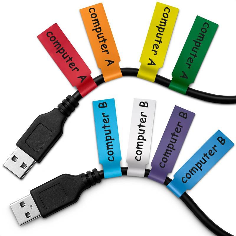
How Do Ethernet and Network Cable Color Codes Work?
Ethernet and network cable color codes help identify cable function, performance, and application. While not enforced by global standards, most IT teams use color conventions—blue for data, yellow for PoE, red for VoIP or critical systems, and green for crossover links—to simplify troubleshooting, speed up installations, and improve data center organization.
Why Ethernet Cable Colors Matter
Unlike electrical wiring, Ethernet colors are not legally standardized under ANSI/TIA or ISO/IEC. However, organizations develop internal color codes to:
- Reduce troubleshooting time: Quickly trace critical connections
- Organize complex networks: Data centers with thousands of cables need visual order
- Improve safety: Separate PoE (Power over Ethernet) from data-only lines
- Support documentation: Consistent color schemes make network diagrams easier to read
Example: A financial institution used to spend 6 hours tracing failed VoIP lines. After standardizing red for all VoIP cables, repair time dropped to 30 minutes.
Typical Ethernet Cable Color Meanings
While practices vary, here’s a widely adopted color convention used in many enterprises:
| Color | Common Use Case | Reason for Choice |
|---|---|---|
| Blue | Standard LAN connections | Default color for data networks |
| Yellow | PoE (Access points, cameras) | High visibility for power-carrying cables |
| Red | VoIP phones, emergency circuits | Stands out for critical lines |
| Green | Crossover or test connections | Traditionally used in testing environments |
| Black | Outdoor/UV-resistant cabling | Weatherproof jackets commonly used outdoors |
| Orange | Demarcation or ISP handoff points | Used for network boundaries |
| Purple | Guest networks or experimental systems | Separate from main production traffic |
| White/Grey | Interconnection jumpers or neutral data | Low-priority links, secondary connections |
Tip: Always include a color legend in rack diagrams and patch panels for quick reference.
Patch Panel and Data Center Cable Color Management
Large-scale networks often rely on structured cabling systems with organized patch panels. Color coding helps:
- Identify different floors, departments, or VLANs
- Separate production, backup, and testing environments
- Trace cross-connects between equipment racks
Example Setup:
- Blue = Standard data links
- Yellow = Security cameras (PoE)
- Red = Emergency/critical circuits
- Green = Backup or redundant links
This system allows technicians to locate faulty circuits in minutes instead of hours.
PoE (Power over Ethernet) Cable Colors
Power over Ethernet delivers both data and electrical power through the same cable to devices like:
- IP cameras
- Wi-Fi access points
- VoIP phones
Because PoE carries up to 90W on some standards (IEEE 802.3bt), many IT departments use yellow cables to distinguish PoE circuits from standard data lines for safety and maintenance clarity.
TIA/EIA and ISO/IEC Standards on Ethernet Colors
Here’s the key point: TIA/EIA-568 and ISO/IEC 11801 only define:
- Cable performance categories (Cat5e, Cat6, Cat6A, Cat7, Cat8)
- Connector pinouts (T568A, T568B)
They do not mandate insulation colors for outer jackets.
However, some regional and industry-specific guidelines exist:
- U.S. DoD Networks: Yellow = Top Secret, Red = Secret, Blue = Unclassified
- Telecom Facilities: Orange = Demarcation points, Blue = Termination panels
Industrial and Harsh-Environment Ethernet Color Codes
Industrial Ethernet (e.g., Profinet, EtherCAT) often uses:
- Green cables: Machine-to-controller connections
- Yellow cables: Controller-to-controller links
- Blue cables: Non-real-time data or diagnostics
This convention helps maintenance teams visually separate critical control lines from standard network traffic.
Example: A German automotive plant reduced downtime by 40% after adopting standardized Profinet color codes across all production lines.
Common Mistakes in Ethernet Cable Color Usage
- No documentation: Colors lose meaning if not standardized company-wide
- Mixing data and power: Increases troubleshooting difficulty
- Color shortages: Bulk cable suppliers sometimes lack specific colors—leading to ad-hoc changes and confusion
- Legacy vs new standards: Old installations may use different schemes, requiring careful transition planning
Do Cable Colors Differ by Application and Industry?
Yes. Cable color codes vary widely across industries and applications. Electrical power systems, data networks, industrial automation, automotive, marine, aerospace, and telecom all use different color schemes to improve safety, streamline maintenance, and comply with sector-specific standards like NEC, IEC, TIA, or MIL-SPEC.
Electrical Power Systems
Electrical installations for residential, commercial, and industrial buildings typically follow:
- NEC (North America)
- IEC 60446 (Europe, Asia, Africa)
| Conductor Function | NEC Color (U.S.) | IEC Color (Europe) | Typical Use Case |
|---|---|---|---|
| Ground / Protective Earth | Green / Green-Yellow | Green-Yellow | Safety grounding |
| Neutral | White / Gray | Blue | Return path in AC circuits |
| Line / Phase 1 | Black | Brown | Single-phase power |
| Line / Phase 2 | Red | Black | 3-phase systems |
| Line / Phase 3 | Blue | Gray | 3-phase systems |
Example: A factory in Germany importing U.S. machinery had to rewire all phases from black-red-blue to brown-black-gray to pass CE inspection.
Data and Telecom Networks
Data centers, telecom rooms, and IT facilities often adopt ANSI/TIA-606-B and ISO/IEC 11801 for labeling, but color conventions are internal, not enforced.
| Cable Color | Common Data/Telecom Usage | Reason for Choice |
|---|---|---|
| Blue | Standard LAN data links | Widely available, default choice |
| Yellow | Power over Ethernet (PoE) circuits | Distinguishes power-carrying lines |
| Red | VoIP phones, critical systems | High visibility for emergency circuits |
| Orange | Demarcation points or ISP handoff | Separates network provider interfaces |
| Green | Crossovers or test circuits | Used in diagnostics and lab setups |
| Purple | Guest networks or experimental VLANs | Avoids confusion with production systems |
Case Study: A U.S. hospital standardized yellow = PoE, red = critical alerts, blue = standard data across 4,000 Ethernet drops. Troubleshooting time fell by 60%, minimizing downtime for life-support systems.
Industrial Automation and Manufacturing
Industrial facilities use PLC (Programmable Logic Controller) wiring, 24V DC control circuits, and fieldbus networks requiring clear visual separation.
| Color | Typical Industrial Meaning | Standard / Practice |
|---|---|---|
| Orange | Interlock / safety circuits | NFPA 79 (U.S. Machine Standard) |
| Blue | 24V DC control voltage | EN 60204-1 |
| Gray | Fieldbus signals (e.g., Profibus, Modbus) | IEC / Vendor-specific |
| Green-Yellow | Protective Earth (PE) | IEC |
Example: A packaging plant used orange wires for safety interlocks so technicians could instantly identify circuits controlling emergency stop buttons.
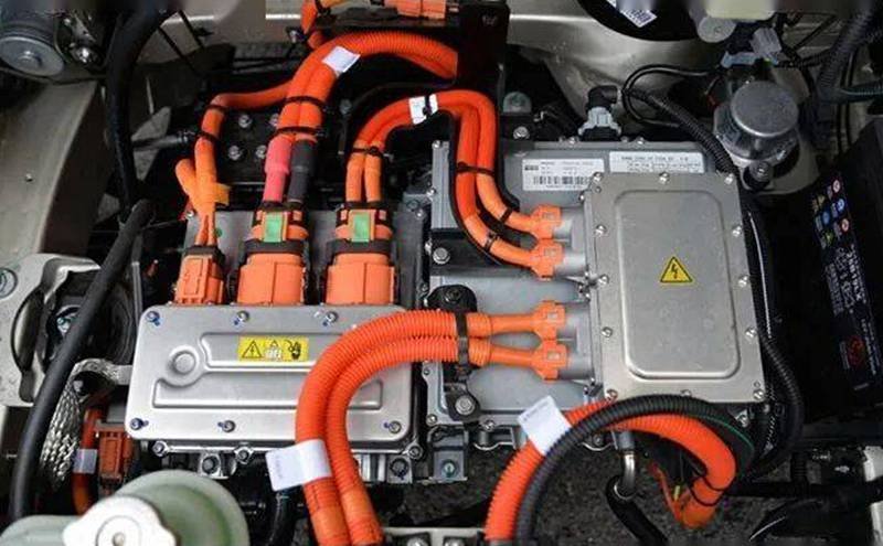
Automotive and Electric Vehicles (EVs)
Automotive wiring harnesses follow ISO 6722 and manufacturer-specific standards. Colors indicate both voltage and function.
| Color | Function in Automotive Wiring | Example Application |
|---|---|---|
| Red | Battery positive | Starter, alternator circuits |
| Black | Ground / chassis negative | Common ground points |
| Yellow | Airbag circuits | Safety restraint systems |
| Blue | Lighting circuits | Headlights, indicators |
| Orange | High-voltage EV cables (>60V DC) | Electric vehicle battery packs |
EV Safety Note: Orange high-voltage cables in EVs warn technicians of lethal DC voltages exceeding 400V.
Marine and Offshore Applications
Marine wiring follows ABYC (American Boat & Yacht Council) or IEC 60092 standards for corrosion resistance and safety.
| Color | Marine Wiring Use | Notes |
|---|---|---|
| Red | DC Positive | Main power distribution |
| Yellow | DC Negative (new standard) | Replacing older black negative |
| Black | DC Negative (legacy standard) | Still found in older vessels |
| Green | AC Grounding | Safety bonding |
Example: A shipyard switched from black to yellow DC negative per ABYC E-11 2018 revision to reduce shock hazards during maintenance.
Aerospace and Defense
Military and aerospace wiring harnesses comply with MIL-STD-681 and AS50881 standards.
| Color | Defense/Aerospace Function | Typical Usage |
|---|---|---|
| Yellow | Top-secret data circuits | U.S. DoD Networks |
| Red | Sensitive / critical power circuits | Weapon systems |
| Blue | Unclassified systems | Non-critical avionics |
| White | Lighting and instrument panel wiring | Aircraft cockpit systems |
Example: NATO aircraft use white wires for cockpit lighting so technicians can instantly identify low-voltage lighting harnesses among power bundles.
Building Security and Fire Alarm Systems
Fire and security codes (e.g., NFPA 72) require specific colors for life-safety circuits.
| Color | Application | Reason |
|---|---|---|
| Red | Fire alarm circuits | High visibility for emergency use |
| Yellow | CCTV and access control | Distinct from fire wiring |
| Blue | Intrusion detection systems | Security system separation |
Example: Fire inspectors often require red jacket fire alarm cables to remain visually distinct from other low-voltage systems.
Renewable Energy Systems (Solar, Wind, Battery Storage)
Solar PV installations follow NEC Article 690 for DC wiring color conventions.
| Color | Solar PV Wiring Function | Typical Application |
|---|---|---|
| Red | DC Positive conductor | PV string wiring |
| Black | DC Negative conductor | PV return wiring |
| Green | Equipment grounding | Array frames, enclosures |
Safety Note: Color-coding PV circuits helps prevent reverse polarity connections that could damage inverters or battery systems.
Comparative Table: Industry-Specific Cable Colors
| Industry | Live/Power | Neutral/Return | Ground/Earth | Control/Signal | Special Functions |
|---|---|---|---|---|---|
| Residential/Commercial | Black/Brown | White/Blue | Green/Green-Yellow | Orange (interlock) | Red (Fire alarm) |
| Data/Telecom | Yellow (PoE) | N/A | N/A | Blue (LAN), Red (VoIP) | Orange (Demarcation) |
| Industrial Automation | Brown (L1), Black(L2) | Blue (24V DC return) | Green-Yellow | Gray (Fieldbus) | Orange (Safety circuits) |
| Automotive / EV | Red (Battery +) | Black (Ground) | Chassis Ground | Yellow (Airbag), Orange (HV) | Blue (Lighting) |
| Marine / Offshore | Red (DC +) | Yellow / Black (DC -) | Green (AC Ground) | N/A | Blue (Bilge pumps) |
| Aerospace / Defense | Red (Critical) | N/A | N/A | White (Cockpit lighting) | Yellow (Top Secret) |
| Renewable Energy (PV) | Red (DC +) | Black (DC -) | Green (Ground) | N/A | N/A |
How Are Electrical Safety and Circuit Identification Linked to Colors?
Electrical safety and circuit identification rely on standardized color codes to prevent wiring mistakes, short circuits, and potential injuries. By assigning specific colors to live, neutral, ground, and control conductors, technicians can quickly identify circuit function without guesswork. This visual language, when aligned with standards like NEC, IEC, and NFPA, reduces installation errors, speeds up maintenance, and ensures global compliance in residential, industrial, and commercial environments.
Core Safety Functions of Color Coding
Color coding serves three main safety purposes: identifying conductors by function, separating voltage levels, and distinguishing emergency circuits. For instance, using green or green-yellow for grounding wires ensures that technicians can immediately recognize safety earth connections, while red often signifies emergency power or fire alarm systems. Such differentiation prevents accidental cross-connections that could lead to equipment damage or personnel hazards.
International Standards for Electrical Wiring Colors
Two dominant standards guide global wiring colors: the NEC (U.S.) and IEC (Europe and many international regions). For example, under the NEC, black represents live (L1), white or gray indicates neutral, and green denotes ground. In contrast, IEC uses brown for L1, blue for neutral, and green-yellow for protective earth. Facilities exporting machinery must document and often dual-label conductors to comply with both standards simultaneously.
Role of Color Codes in Circuit Identification
Color coding goes beyond power wiring to include control, signaling, and isolated power circuits. For instance, NFPA 79 mandates orange conductors for circuits energized when the main disconnect is off, warning technicians before they begin maintenance. Similarly, hospitals often use yellow wires for isolated power systems in operating rooms, ensuring critical life-support systems remain safe and properly identified.
Benefits for Troubleshooting and Maintenance
Standardized wiring colors reduce troubleshooting time dramatically. When technicians open a control panel, instantly recognizing blue wires as DC control circuits or red as emergency power circuits eliminates guesswork. A semiconductor plant that standardized yellow for isolated ground circuits reported reducing fault diagnosis time from three hours to under one hour per incident, minimizing downtime and operational losses.
Voltage and Phase Separation Using Colors
In three-phase systems, different colors distinguish each phase, ensuring correct motor rotation and balanced load distribution. For example, NEC commonly uses black, red, and blue for phases L1, L2, and L3, while IEC standards prefer brown, black, and gray. Similarly, low-voltage DC control circuits often use blue wiring, separating them visually from higher-voltage AC power conductors to prevent accidental cross-connections.
Emergency and Life-Safety Circuit Identification
Life-safety systems rely heavily on color coding for quick recognition. Fire alarms typically use red cables, emergency lighting circuits may use orange, and hospital critical-care power circuits often use yellow. During emergencies, first responders and technicians can identify and prioritize these circuits instantly, preventing delays that could endanger lives or critical operations.
Lockout/Tagout (LOTO) and Safety Compliance
Lockout/Tagout procedures require circuits to be fully de-energized before maintenance. Color-coded wiring supports LOTO by visually confirming conductor function before technicians test or lock circuits. When combined with printed labels and digital documentation, color coding becomes part of a multilayered safety approach meeting OSHA, NFPA, and IEC compliance requirements.
Global and Multi-Voltage Facility Challenges
Modern industrial facilities often combine AC power, DC controls, emergency systems, and IT networks in the same building. Without strict color conventions, wiring errors become inevitable, especially when multiple voltage classes share conduits or panels. Adopting global standards like IEC 60446, along with bilingual labels and CAD-documented color schemes, ensures consistency across international sites.
How Do Installation, Maintenance, and Communication Benefit from Color Coding?
Color-coded wiring simplifies installation, accelerates maintenance, and improves team communication by visually identifying circuits, voltages, and safety-critical systems. Standardized colors reduce wiring errors, minimize downtime, and help cross-functional teams coordinate efficiently. Facilities using consistent color schemes report faster troubleshooting, safer operations, and lower long-term maintenance costs.
1. Faster and Error-Free Installation
During new construction or equipment commissioning, electricians often work under tight deadlines. Color coding provides an immediate visual guide, eliminating the need to check each conductor with a multimeter before termination.
- Time Savings: A study by the National Electrical Contractors Association (NECA) showed that projects using standardized color codes experienced 30% faster wiring completion compared to projects without color coding.
- Reduced Errors: Visual differentiation of live, neutral, and ground circuits prevents dangerous miswirings that could lead to short circuits or equipment failures.
Example: A data center in Singapore adopted TIA/EIA-606-B labeling plus a standardized color scheme: blue for data, yellow for PoE, and red for critical power. As a result, the facility reported zero wiring-related startup delays across three phases of expansion.
2. Simplified Preventive and Corrective Maintenance
Maintenance crews frequently handle panel modifications, retrofits, and fault diagnosis. Color-coded wiring allows them to:
- Trace circuits visually without repeatedly consulting schematics
- Identify high-voltage vs. low-voltage systems instantly
- Distinguish emergency or life-safety circuits from standard circuits
Impact on Downtime: A semiconductor facility in Germany reported that adopting IEC-compliant color codes reduced average fault isolation time from 2 hours to 40 minutes.
Case Study Table: Maintenance Efficiency Before vs. After Standardized Color Coding
| Parameter | Before Color Coding | After Color Coding | Improvement |
|---|---|---|---|
| Average Fault Isolation Time | 120 min | 40 min | 67% faster |
| Panel Modification Errors | 5 per 100 interventions | 1 per 100 interventions | 80% reduction |
| Emergency Circuit Misidentification | 3 per year | 0 per year | 100% elimination |
3. Enhanced Safety Compliance
Safety codes such as NEC (U.S.), IEC (Europe), and NFPA 79 (industrial machinery) require clear identification of conductors. Color coding helps facilities meet:
- Lockout/Tagout (LOTO) standards for de-energizing circuits
- OSHA workplace electrical safety regulations
- NFPA 70E arc flash hazard prevention guidelines
Example: Hospitals use yellow-coded isolated power systems in operating rooms to prevent power interruptions to life-support equipment, meeting both NFPA and IEC medical safety requirements.
4. Improved Communication Across Teams
Modern facilities involve electrical engineers, IT staff, maintenance crews, and safety officers working together. Color coding provides a universal visual language across departments and even across borders.
- Technicians see red circuits and immediately know they power emergency lighting.
- IT teams recognize blue cables as standard Ethernet links, yellow as PoE circuits.
- Contractors performing expansions can follow existing color conventions without confusion.
5. Streamlined Documentation and Training
Color coding complements CAD-based wiring diagrams and digital twin models by providing a physical match to documented standards.
- Training Time Reduction: New technicians learn facility wiring conventions 40% faster when visual color cues match printed schematics.
- Digital Integration: QR-coded labels plus color coding enable augmented reality (AR) maintenance apps to highlight circuits dynamically on a technician’s tablet or AR headset.
6. Life-Cycle Cost Reduction
Though initial installation with standardized color codes may cost slightly more (e.g., multiple cable jacket colors, printed legends), the total cost of ownership (TCO) drops over the system’s lifetime:
- Fewer wiring mistakes lower rework costs
- Faster troubleshooting reduces downtime penalties
- Simplified training cuts labor expenses
TCO Comparison Over 10 Years
| Parameter | Non-Standard Wiring | Color-Coded Wiring | Savings Over 10 Years |
|---|---|---|---|
| Average Downtime Costs | $500,000 | $300,000 | $200,000 |
| Rework Labor Costs | $120,000 | $50,000 | $70,000 |
| Technician Training Expenses | $80,000 | $50,000 | $30,000 |
7. Industry-Specific Benefits
- Data Centers: Color coding separates backup power (red), PoE circuits (yellow), and standard data (blue) for Tier 3/Tier 4 reliability compliance.
- Automotive Plants: Orange conductors mark interlock circuits that stay energized for robotics safety systems, reducing accident risks.
- Pharmaceutical Manufacturing: Green/yellow grounding circuits ensure compliance with ATEX explosion-proof regulations in hazardous zones.
8. Future Trends: Smart Color Coding + Digital Tags
Next-generation systems combine traditional color schemes with QR codes, RFID tags, and digital twin models. This hybrid approach enables:
- Instant access to circuit data via mobile devices
- Automated compliance checks with AI-powered facility software
- Multilingual documentation embedded into digital labels for global teams
Future Trends: Will There Ever Be a Global Standard?
A truly global cable color standard does not exist yet due to regional regulations, legacy systems, and industry-specific needs. However, organizations like IEC, IEEE, and ISO are pushing for harmonization, while smart labeling, digital twins, and Industry 4.0 technologies may bridge differences in the future. Full convergence may take decades, but progress is underway.
Ongoing Efforts Toward Harmonization
International organizations are slowly pushing for convergence:
- IEC (International Electrotechnical Commission): Publishes IEC 60446 and IEC 60364 for low-voltage installations; many countries adopt or adapt these guidelines.
- IEEE (Institute of Electrical and Electronics Engineers): Proposes best practices for industrial wiring but leaves room for regional adaptation.
- ISO (International Organization for Standardization): Focuses on manufacturing and labeling harmonization, encouraging shared color codes for industrial automation.
- NFPA & NEC: U.S.-based organizations periodically revise codes, sometimes aligning partially with IEC conventions.
Example: In 2001, the EU mandated brown, black, and gray for three-phase conductors, aligning partially with IEC, while the U.K. switched from red-yellow-blue to the IEC scheme in 2004. This shows gradual—but not universal—movement toward harmonization.
Technology’s Role in Future Standardization
Emerging technologies may reduce reliance on color alone for circuit identification:
- Smart Labels & QR Coding
- Cables printed with QR codes or RFID tags could store voltage, circuit ID, and maintenance history.
- Maintenance crews scan cables rather than rely solely on colors.
- Digital Twin Integration
- Facilities use 3D digital models with real-time wiring schematics, allowing technicians to trace circuits virtually before working on them.
- Augmented Reality (AR) Maintenance
- AR headsets could overlay circuit functions, voltage ratings, and safety instructions directly onto a technician’s field of view.
- AI-Powered Cable Management
- Predictive analytics can recommend color schemes or tagging methods optimized for safety, maintenance speed, and error reduction.
Regional vs Global Convergence: Likely Future Scenarios
Experts predict three possible outcomes for the next 20–30 years:
| Scenario | Description | Probability | Impact on Industry |
|---|---|---|---|
| Global Unified Standard | One worldwide code replaces NEC, IEC, JIS, etc. | Low | High implementation cost, decades to adopt |
| Regional Alignment | NEC & IEC converge gradually on phase & ground | Medium | Easier trade, fewer wiring errors |
| Hybrid Digital Approach | Colors + Smart Labels + Digital Twins coexist | High | Maximum flexibility, lowest disruption |
Most experts consider the Hybrid Digital Approach the most realistic, combining traditional colors for quick visual ID with smart labeling for detailed data.
Cross-Border Manufacturing Challenges
Global manufacturers like automotive OEMs, data center operators, and aerospace suppliers often export equipment across multiple regulatory regions. Without standardization, they face:
- Multiple wiring diagrams per region
- Dual-labeled cables (color + printed text)
- Higher inventory costs for region-specific harnesses
- Increased training complexity for multinational teams
Sustainability and Standardization Pressure
Environmental regulations such as RoHS, REACH, and WEEE increasingly demand simplified, recyclable wiring systems. A global standard could:
- Reduce manufacturing waste by standardizing cable jackets and labeling materials
- Simplify end-of-life recycling through color-coded disassembly processes
- Support circular economy goals in automotive and electronics industries
Timelines: When Could We See Convergence?
- Near-Term (5–10 years): Expect more countries to adopt IEC colors for low-voltage installations, especially in Asia, Africa, and Latin America.
- Mid-Term (10–20 years): Hybrid systems with colors + digital tags become mainstream in industrial facilities and smart buildings.
- Long-Term (20–30 years): Partial convergence between NEC and IEC likely, but full global standardization remains uncertain due to legacy infrastructure.
Industry 4.0 and Smart Factories: A Game-Changer
The rise of Industry 4.0 and smart manufacturing will accelerate changes:
- Automated cable printing enables on-demand color + text labeling at installation sites.
- IIoT-enabled panels track wiring integrity and maintenance needs digitally.
- Robotic installation systems follow standardized labeling protocols for error-free wiring in mass production.
Preparing for the Future: Recommendations for Engineers & Buyers
- Adopt Dual-Labeled Cables: Combine color coding with printed text or digital IDs for future-proof installations.
- Work With Global Suppliers: Manufacturers like Sino-Conn provide custom harnesses meeting NEC, IEC, and UL simultaneously.
- Stay Updated on Code Revisions: NEC updates every three years; IEC standards evolve regularly.
- Invest in Digital Cable Management: Use software and QR-based cable labeling for complex projects.
- Train Multinational Teams: Standardize internal company practices even if external codes differ.
Conclusion
Color-coded cables save time, prevent accidents, and ensure compliance across industries—from residential electricians to aerospace engineers. But success depends on selecting the right standard, supplier, and documentation process for your region and application.
Contact Sino-Conn today for CAD drawings, samples, or a custom wiring solution tailored to your project’s safety and compliance needs.